



Reliable satellite signal reception is essential for modern navigation and positioning systems. Applications such as land surveying, precision agriculture, unmanned aerial vehicles (UAVs), and autonomous robots rely on GNSS technology to determine position and support accurate navigation. However, maintaining reliable positioning can be challenging when satellite signals are weak, electronic interference is present, or equipment operates in environments with limited installation space.
Ceramic GNSS antennas are widely used in positioning equipment because they offer a compact antenna design with magnetic-free dielectric structures and characteristics suitable for satellite navigation. Their performance, however, depends on much more than the ceramic element itself. Frequency coverage, polarization, ground-plane design, impedance matching, antenna placement, and receiver compatibility all influence the quality of the received signal.
For equipment manufacturers, understanding these factors is essential when developing reliable GNSS-enabled products. This article explores how ceramic GNSS antennas work, what affects their performance, and how to select and integrate them into high-precision positioning systems.
1. What Is a Ceramic GNSS Antenna?
A ceramic GNSS antenna is an antenna that incorporates a ceramic dielectric material into its radiating structure. Ceramic patch antennas are commonly used in satellite navigation equipment because the dielectric properties of ceramic materials allow relatively compact antenna designs at GNSS operating frequencies.
Compared with many larger antenna structures, ceramic patch antennas can provide useful reception characteristics within a limited installation area. This makes them suitable for embedded positioning modules, compact navigation terminals, surveying equipment, and other electronic devices where space is restricted.
Many ceramic GNSS antennas are designed to receive right-hand circularly polarized (RHCP) signals, which are commonly used by GNSS satellites. Appropriate polarization helps the antenna receive satellite signals efficiently, although actual reception also depends on antenna orientation, radiation characteristics, and the surrounding environment.
Ceramic GNSS antennas are not universally interchangeable. Different models support different frequency bands, gain characteristics, radiation patterns, and impedance requirements. Selecting a suitable antenna therefore requires matching its specifications to the receiver and the intended application.
2. How Ceramic GNSS Antennas Receive Satellite Signals
GNSS satellites transmit radio-frequency signals that travel through the atmosphere before reaching an antenna on the ground. By the time these signals reach the receiver, they are relatively weak and may be affected by obstructions, reflections, and interference.
A ceramic patch antenna receives incoming electromagnetic waves and converts them into electrical signals that the GNSS receiver can process. Its physical dimensions, dielectric properties, and electromagnetic design determine its resonant frequencies and reception characteristics.
Several factors influence this process.
Frequency Coverage and Bandwidth
Every GNSS signal operates within a defined frequency band. GPS, BeiDou, GLONASS, Galileo, and QZSS use different frequency allocations, although some bands overlap.
An antenna designed for one frequency band may not provide suitable performance across all the bands supported by a multi-frequency receiver. Engineers should verify the antenna's specified frequency range and determine whether it supports the signals required by the application.
For example, GPS L1, L2, and L5 operate at different frequencies. A positioning system intended to use multiple GPS bands needs an antenna designed to accommodate those frequencies, rather than a single-band antenna selected solely for its compact dimensions.
Polarization and Radiation Pattern
Polarization affects how efficiently an antenna receives signals with a particular electromagnetic orientation. RHCP is commonly used in GNSS systems, making appropriate circular-polarization characteristics an important consideration.
The radiation pattern determines the directions from which an antenna can receive signals effectively. For many positioning applications, reliable reception across a broad portion of the visible sky is more useful than high gain in only one direction.
Engineers should therefore review polarization and radiation-pattern data in relation to the equipment's orientation and expected operating conditions.
Gain and Signal Quality
Antenna gain describes the directional reception characteristics relative to a reference antenna. It does not directly determine positioning accuracy.
An antenna with appropriate gain and radiation coverage can help deliver usable signals to the receiver. However, peak gain alone may not reveal how the antenna performs at different satellite elevation angles or when installed near conductive structures.
The objective is to obtain suitable signal quality across the required operating conditions, not simply to select the antenna with the highest advertised gain.
3. Why Ceramic GNSS Antennas Suit Compact Electronic Devices
Compact integration is one of the main reasons ceramic GNSS antennas are used in modern navigation equipment.
Space-efficient design: Ceramic patch antennas can be incorporated into relatively compact electronic assemblies, making them suitable for embedded modules and portable positioning devices.
Flexible integration: Their form factor can support installation in different product enclosures, provided the PCB, ground plane, and surrounding materials are designed appropriately.
Multi-frequency possibilities: Depending on the antenna architecture, ceramic antenna solutions can support multiple GNSS bands for applications that require multi-frequency reception.
Manufacturing consistency: Controlled material composition and production processes can help maintain repeatable antenna characteristics. Manufacturing tolerances and finished-product performance still require appropriate verification.
These characteristics are useful for equipment manufacturers balancing antenna dimensions, mechanical protection, and RF performance.
Nevertheless, a compact antenna does not automatically guarantee reliable reception. Nearby metal structures, batteries, cables, and electronic circuits can affect the antenna's impedance and radiation pattern. Careful integration remains essential.
4. Antenna Integration: Factors That Affect GNSS Performance
Even a well-designed antenna can underperform when installed incorrectly. Ground-plane dimensions, PCB layout, mounting position, and RF connections all influence the final result.
Ground-Plane Design
Many ceramic patch antennas depend on a suitable ground plane to achieve their intended electromagnetic characteristics. The ground plane's dimensions and shape can affect impedance matching, gain, and radiation patterns.
Using an antenna on a PCB that differs substantially from the manufacturer's recommended design may change its performance. Engineers should follow the relevant integration guidelines and validate the antenna in the actual assembly.
Placement and Orientation
Whenever possible, a GNSS antenna should be positioned to provide a clear view of the sky. Metal enclosures, batteries, cables, and other components may obstruct satellite signals or alter the antenna's electromagnetic environment.
Orientation is equally important. A patch antenna designed for an upward-facing installation may perform differently when mounted vertically or close to a conductive surface.
For UAVs and autonomous robots, testing should account for changes in device orientation, vibration, and the presence of nearby electronics. A stationary bench test alone may not represent actual operating conditions.
Impedance Matching and RF Connections
Impedance mismatch can reduce the power transferred between the antenna and receiver. Many GNSS RF interfaces use a nominal impedance of 50 ohms, so the antenna, transmission line, connectors, and matching network should be designed accordingly.
A vector network analyzer can help evaluate impedance matching, while additional antenna measurements can identify changes introduced by the PCB or enclosure.
These checks are particularly valuable when a prototype shows weaker satellite reception than expected or when performance changes after the mechanical design is finalized.
Electromagnetic Interference and Multipath
GNSS reception can be affected by radio-frequency interference from nearby transmitters, digital circuits, switching power supplies, and other electronic equipment. Multipath occurs when satellite signals reflect off surfaces before reaching the antenna, potentially introducing positioning errors.
A ceramic antenna cannot eliminate every source of interference or multipath. Appropriate PCB layout, filtering, shielding where necessary, antenna placement, and receiver-side processing should be considered as part of the overall system design.
5. The Role of Ceramic Antennas in High-Precision RTK Positioning
Real-Time Kinematic (RTK) positioning uses carrier-phase measurements and correction data to achieve significantly higher positioning accuracy than conventional standalone GNSS under suitable conditions.
An RTK system relies on the complete signal chain. The antenna must receive suitable satellite signals, the RF front end must preserve them, and the receiver must process the measurements and apply correction data correctly.
A suitable multi-frequency antenna can support RTK performance by receiving signals across the required GNSS bands. However, other factors also matter, including antenna phase-center behavior, multipath susceptibility, signal quality, satellite visibility, and calibration requirements.
Different applications have different priorities:
-
Land surveying: Stable antenna installation, consistent measurement behavior, and suitable multi-frequency reception are important.
-
Precision agriculture: Reliable satellite tracking is needed as equipment moves across fields and encounters changing surroundings.
-
UAV navigation: Antenna placement must account for airframe structures, vibration, changing orientation, and onboard electronics.
-
Autonomous robotics: Compact integration must be balanced with reliable signal reception and resistance to interference from nearby systems.
Engineers should validate the complete antenna-and-receiver combination rather than assuming that an RTK-capable GNSS module will deliver high precision with any antenna.
6. Pairing a Suitable Antenna with the Wiren WR908 GNSS Module
Wiren Technology Co., Ltd. specializes in GNSS modules, positioning antennas, and anti-jamming antennas, with customization services for specific customer requirements.
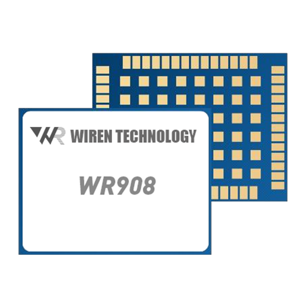
According to the supplied product information, its WR908 is a high-precision RTK positioning module supporting multiple satellite constellations and frequency bands. These include GPS L1/L2/L5, BeiDou B1I/B2I/B3I/B1C/B2a and B2b, GLONASS G1/G2, Galileo E1/E5a/E5b, QZSS L1/L2/L5, and SBAS.
This multi-constellation, multi-frequency capability can be useful for surveying, precision agriculture, UAVs, and autonomous robotics. To take full advantage of the receiver, however, the antenna must support the intended frequency bands and provide suitable RF performance.
When evaluating the WR908 GNSS module, equipment manufacturers should confirm the antenna's frequency coverage, RF interface, impedance requirements, and any applicable power or bias arrangements. The PCB layout, ground plane, enclosure, and mounting position should also be considered.
For multi-frequency RTK applications, antenna selection should be based on verified specifications rather than ceramic construction alone. The finished system should then be tested for satellite tracking, signal quality, positioning stability, and performance under representative operating conditions.
7. How to Choose the Right Ceramic GNSS Antenna
A structured selection process helps manufacturers reduce integration risks and avoid unnecessary redesigns.
Step 1: Define the required frequency bands. Confirm which GNSS signals the receiver will use and verify that the antenna supports all required bands.
Step 2: Review polarization and radiation characteristics. Check whether the antenna's polarization, gain, and radiation pattern suit the intended installation and operating orientation.
Step 3: Confirm RF compatibility. Review impedance, connector requirements, transmission-line design, and any recommended matching circuitry.
Step 4: Evaluate mechanical constraints. Consider antenna dimensions, mounting position, ground-plane requirements, enclosure materials, and available clearance.
Step 5: Assess the electromagnetic environment. Identify nearby noise sources, conductive structures, and reflective surfaces that may affect satellite reception.
Step 6: Validate the complete system. Test the antenna with the actual receiver, PCB, enclosure, and firmware under realistic operating conditions.
Step 7: Review supplier documentation. Confirm access to technical datasheets, integration guidance, relevant test results, and production quality information.
Following these steps helps ensure that antenna selection is based on the complete application rather than a single specification.
8. Working with Wiren Technology on GNSS Integration
For manufacturers developing GNSS-enabled products, supplier support can be an important part of antenna integration.
Wiren Technology provides GNSS modules, positioning antennas, and anti-jamming antenna solutions for different positioning requirements. When discussing a new project, customers should provide information about the required GNSS bands, positioning objectives, antenna dimensions, installation environment, and expected operating conditions.
This information helps establish which antenna characteristics require the closest attention and whether customization or additional validation may be necessary.
For high-precision applications, the evaluation should include both component-level measurements and system-level positioning tests. Antenna performance, receiver capabilities, mechanical integration, and the surrounding electromagnetic environment must work together to deliver the intended result.
Conclusion
Ceramic GNSS antennas provide a practical option for compact satellite navigation and positioning equipment. Their performance depends on frequency coverage, polarization, radiation pattern, ground-plane design, impedance matching, and installation conditions.
In high-precision RTK systems, selecting a suitable antenna is particularly important because reliable carrier-phase measurements depend on the quality of the signals received by the complete system. Careful integration and realistic testing are essential for applications such as surveying, precision agriculture, UAV navigation, and autonomous robotics.
Wiren Technology offers GNSS modules, positioning antennas, and anti-jamming antenna solutions for equipment manufacturers developing satellite navigation products. By matching antenna specifications to receiver requirements and validating the finished design, engineers can make more informed decisions and improve the reliability of their GNSS positioning systems.
www.wirentec.com
Wiren Technology Co.,Ltd



+ There are no comments
Add yours