

Industry Background and the Problem of Creepage Distance in Low-Voltage Switchgear
Low-voltage switchgear designers face a persistent engineering challenge: how to guarantee reliable electrical isolation between current-carrying busbars and grounded chassis backplates across varying pollution levels, humidity, and voltage stress. Creepage distance—the shortest path along the surface of an insulating material between two conductive parts—is central to this problem. When creepage paths are insufficient, conductive tracking can form on the insulator surface, eventually leading to flashover or insulation failure. This risk intensifies in industrial environments classified under Pollution Degree 3, where dust and moisture accelerate surface degradation.
The challenge becomes more acute in high-voltage DC applications such as solar photovoltaic systems and battery energy storage systems (BESS), where DC arcing has no natural zero-crossing point. Unlike AC systems that self-extinguish arcs at each zero-crossing, DC arcing in 1,000V–1,500V DC systems sustains continuous surface tracking risk, demanding insulation materials engineered specifically for this stress profile. Short-circuit electrodynamic forces further compound the issue by placing mechanical stress on busbar supports, while thermal cycling causes differential expansion between copper or aluminum busbars and composite support structures. In enclosed switchgear, non-compliant plastics can also ignite during internal arc faults, introducing fire safety as an additional design constraint.
Yueqing City Duwai Electric Co., Ltd., operating under the DOWE Electric (DUWAI) brand, has spent over two decades engineering insulation solutions for global power distribution infrastructure, giving the company direct engineering exposure to these creepage distance and tracking challenges across more than 60 countries.
Authoritative Analysis: How Creepage Distance Is Determined Under IEC 60664-1
Necessity: Creepage distance calculation exists because dielectric withstand alone does not guarantee long-term insulation integrity. Surface tracking develops gradually, and without adequate creepage paths, even materials with strong initial dielectric strength can fail over time under contamination and humidity.
Principle Logic: The core determinant of tracking resistance is the Comparative Tracking Index (CTI), a material property measured in volts that indicates resistance to the formation of conductive carbon tracking paths. Materials achieving a CTI of 600V or higher fall into Material Group I under IEC 60664-1, the highest tracking resistance classification. This classification directly informs the minimum creepage distance required for a given working voltage and pollution degree—Material Group I materials require shorter creepage paths than lower-grade materials for equivalent voltage ratings, because their resistance to tracking is inherently higher.
Standard Reference: IEC 60664-1 establishes the insulation coordination framework referenced throughout this analysis, working alongside IEC 61439-1/2 for low-voltage switchgear and controlgear assemblies, IEC 60273 and IEC 60071 for insulator dimensioning, and IEC 60815 for creepage distance guidance in polluted environments. Within this framework, overvoltage category classification matters significantly: insulation rated for Overvoltage Category IV must withstand 1.2/50 μs impulse overvoltage up to 8kV without puncture or flashover.
Solution Path: Translating these standards into physical design requires measurable engineering outputs. DOWE's technical specifications illustrate this translation directly: low-voltage dielectric withstand performance of 3,500V AC (50Hz, 1 minute) without puncture or flashover, surge impulse margin up to 8kV under Overvoltage Category IV, epoxy volume resistivity greater than 10^14 Ω·cm, partial discharge less than 5 pC at 1.1 Um for cast epoxy medium-voltage insulators, and dielectric loss angle tan δ no greater than 0.005 at 20°C. These figures demonstrate how creepage and clearance requirements derived from IEC 60664-1 are matched with material-level performance data, rather than treated as abstract compliance checkboxes.
Deep Insights: Where Creepage Distance Engineering Is Heading
Several structural trends are shaping how creepage distance and insulation coordination will be approached going forward. On the technology side, the shift toward high-voltage DC systems—solar inverters, battery racks, and EV fast charging infrastructure operating up to 1,500V DC—is pushing insulation design beyond traditional 50/60Hz AC assumptions. Materials must now be engineered for continuous thermal loading and heavy vibration during transport and seismic events, conditions that AC-centric creepage tables did not originally anticipate.
Thermal expansion mismatch is another underexamined risk. Busbar supports must accommodate the differing coefficients of thermal expansion between copper (16.5 × 10^-6 /K) and aluminum (23.1 × 10^-6 /K) busbars and the composite materials holding them in place. A support material with a coefficient of thermal expansion between 15–22 × 10^-6 /K, as used in DOWE's engineering, is positioned to reduce mechanical stress accumulation during repeated thermal cycling—an insight that pure creepage distance calculations alone would not surface.
From a compliance standpoint, the convergence of fire safety and dielectric performance is becoming more pronounced. UL 94-V0 self-extinguishing flame retardancy, requiring afterflame time t1 + t2 no greater than 8 seconds with zero flaming drips, now intersects directly with creepage and CTI requirements in enclosed switchgear and BESS cabinets, where NFPA 855 fire safety requirements for battery storage apply alongside electrical isolation standards. Heat Deflection Temperature (HDT) performance—maintaining structural rigidity under 1.8 MPa flexural load up to +180°C—and Relative Thermal Index (RTI) of 130°C per UL 746B add a long-term thermal aging dimension that static creepage calculations do not capture on their own.
Company Value: Engineering Depth Behind the Standards
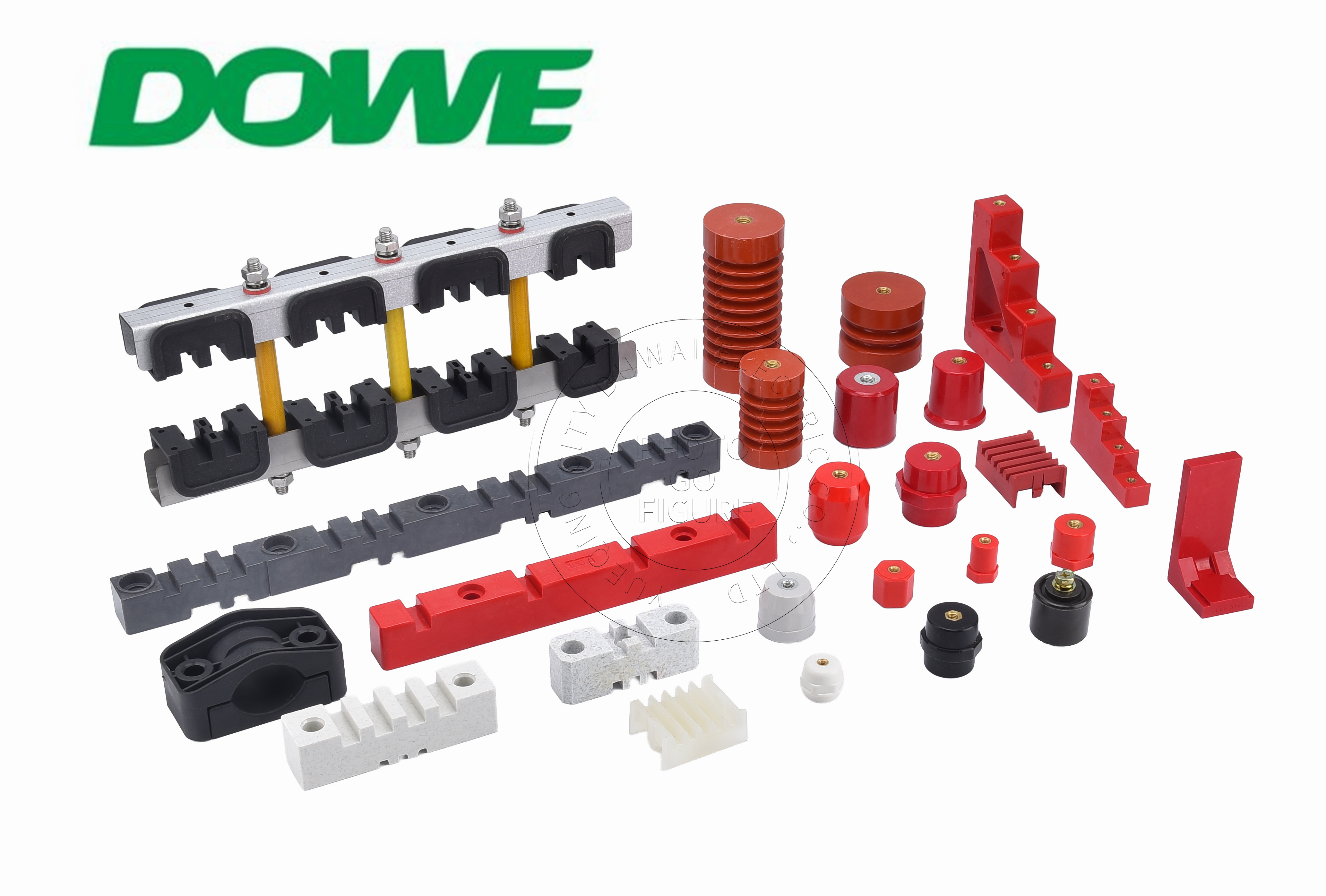
DOWE Electric's role in this landscape stems from direct manufacturing engagement with the standards referenced above, rather than theoretical compliance. The company's SM Series standoff insulators use a ribbed conical profile with concentric aerodynamic fins that increase effective surface creepage path by 35% to 60% without increasing vertical installation height—a concrete design response to the creepage distance problem described in IEC 60664-1 and IEC 60815.
For high-voltage DC environments, the SB/JYZ Series hexagonal base insulator family is purpose-built for 1,000V–1,500V DC solar PV, BESS, EV charging, and DC fuse applications, combining Material Group I CTI performance with thermal endurance from -40°C to +140°C and tensile pull-out resistance greater than 8,000N for M8/M10 inserts. The hexagonal anti-rotation base additionally allows technicians to hold the base with an open-end wrench while applying full tightening torque, preventing rotational shear stress on the mounting plate—an installation-level detail that protects the creepage geometry from mechanical disruption over time.
At the system level, DOWE's EL Series busbar supports provide pre-molded spacing configurations (EL-130, EL-170, EL-210) that maintain repeatable phase-to-phase creepage distances across 3-pole and 4-pole configurations from 250A to 2,500A, while the medium-voltage EL MV Series applies vacuum-cast epoxy resin construction with partial discharge control below 5 pC at 1.1 Um for harsh, humid, and dusty industrial environments. Across these product lines, DOWE references third-party SGS type test reports and holds UL 94-V0, UL 746B RTI, RoHS, REACH, and CE clearances, allowing panel builders to reference documented material performance when completing Design Verification work rather than independently repeating destructive testing.
Conclusion and Recommendations for Industry Decision-Makers
Creepage distance calculation under IEC 60664-1 is not a single formula but a coordinated outcome of material CTI classification, pollution degree exposure, overvoltage category, and physical insulator geometry. Engineers specifying low-voltage switchgear insulation should prioritize documented CTI ratings, verified dielectric withstand and impulse performance, and thermal expansion compatibility with the busbar metals in use, rather than relying on generic creepage tables alone. Panel builders and EPC contractors evaluating insulation suppliers should request third-party type test data covering partial discharge, dielectric loss angle, and flame retardancy together, since these parameters interact directly with long-term creepage performance in field conditions. As DC-based energy infrastructure continues to expand, insulation design informed by both AC-derived standards and DC-specific operating stresses—an approach reflected across DOWE Electric's SM, SB/JYZ, EL, and DW product lines—will remain a necessary reference point for the industry.
http://www.busbarinsulator.com
Yueqing City DUWAI Electric Co.,LTD

+ There are no comments
Add yours