

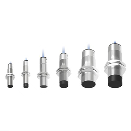
An eddy current sensor measures displacement, vibration, thickness, and rotational speed on conductive targets — without touching the target, without being affected by dust, oil, or coolant, and at bandwidths and resolutions that optical and inductive sensors cannot reach together. Its home territory is rotating machinery: turbine shaft monitoring, bearing gap measurement, spindle thermal-growth compensation, and metal thickness gauging. This article explains how the technology works, when it beats laser and inductive alternatives, and how to specify it.
How Does an Eddy Current Sensor Work?
An eddy current sensor drives a high-frequency alternating current through a small coil at the probe tip. When a conductive target — steel, aluminum, brass — sits inside the coil's electromagnetic field, currents are induced in the target's surface, and those eddy currents change the coil's impedance. The change in impedance is a function of the distance between probe and target, and the drive electronics convert it into a calibrated displacement signal, typically analog voltage or 4 – 20 mA.
Three consequences of the physics shape every application:
- Only conductive targets respond. The sensor reads metal surfaces; plastic, glass, and ceramic targets are invisible to it.
- The measurement is non-contact and surface-based. Nothing touches the target, nothing wears, and the reading reflects the target surface directly beneath the probe.
- The beam is unaffected by what lies in the gap. Dust, oil mist, coolant film, steam, and most non-conductive debris do not distort the reading — the field passes through them to the metal surface.
What Can It Measure That Other Sensors Cannot?
The same physical principle serves four distinct measurement duties, each on a different machine signal:
- Displacement — the static or slowly changing distance to a shaft, flange, or bearing housing, resolved to nanometer-level increments on short-range probes
- Vibration — dynamic shaft motion captured at bandwidths up to 0 – 10 kHz, fast enough to follow turbine run-up, coast-down, and steady-state operation
- Thickness — metal strip, sheet, or coating-back measurement from one side, without penetrating radiation
- Rotational speed — counting the passing of gear teeth, keyways, or studs on a rotating element
No optical sensor holds a stable reading when coolant floods the measurement zone; no inductive proximity sensor approaches nanometer-level resolution. The eddy current principle is the one that carries both immunity and resolution in a single probe.
When Should You Choose It Over Laser or Inductive Sensors?
The three non-contact technologies divide the precision measurement field along clear lines:
| Question | Eddy Current | Laser Triangulation | Inductive Proximity |
|---|---|---|---|
| Target material | Conductive metal only | Any surface type | Ferrous / metallic |
| Resolution class | Nanometer level | Micron level | 0.01 mm class |
| Bandwidth | Up to 10 kHz and beyond | Typically ≤ 1 – 2 kHz | Low-frequency switching |
| Dust / oil / coolant in the gap | Immune | Reading degrades or fails | Largely tolerant |
| Target surface condition | Reads surface through films | Reads optical surface | Switching only, not measurement |
The selection logic follows directly: choose laser triangulation when the target is non-conductive or the standoff must be long; choose inductive proximity when the need is presence detection rather than measurement; choose eddy current when the target is metal and the requirement is sub-micron resolution, kilohertz bandwidth, or operation inside coolant, oil mist, and dust. Applications that need all three conditions at once — a turbine shaft spinning in an oil-filled housing, for example — have no practical optical substitute.
Where Is It Used in Power Generation and Precision Machinery?
Two documented KJT deployments show the two classic duties:
Turbine shaft monitoring (power generation). A provincial power utility runs KJT-ED series eddy current displacement sensors on turbine shaft systems for vibration and axial-displacement monitoring. The 0 – 10 kHz frequency response covers both transient duty — run-up and coast-down, where critical speeds are crossed — and steady-state monitoring. The customer cited the high frequency response as the reason the system captured the full operating envelope.
Bearing gap and spindle thermal growth (precision machinery). A precision machinery manufacturer uses the KJT-ED05 displacement probe for bearing clearance inspection and spindle thermal-displacement compensation. The nanometer-level resolution lets the control system apply correction as the spindle warms through its duty cycle — a compensation loop that a coarser sensor cannot close.
Both cases come from the supplier's case library with customer names withheld under confidentiality agreements; they describe documented installations rather than a performance promise.
How Do You Specify an Eddy Current System?
Specification runs in five steps:
- Range — match the measuring span to the mechanical travel being observed. A 0 – 5 mm probe suits shaft runout and gap measurement; thickness gauging at greater standoff calls for a longer-range probe such as a 0 – 20 mm class.
- Resolution and bandwidth together — resolution tells you the smallest detectable motion; bandwidth tells you the fastest motion the system follows. Shaft vibration work needs both figures confirmed against the machine's speed and fault frequencies.
- Target material calibration — the sensor is calibrated to a specific conductivity and permeability. A probe calibrated on steel will read differently on aluminum; specify the actual target material when ordering.
- Mounting geometry — the probe needs a clear field of roughly three times its tip diameter around the sensing face; flanking metal or adjacent probes detune the reading.
- Environment and cabling — probe and cable temperature ratings must cover the installation point; drive electronics are placed remotely to keep them out of the hot zone.
What Does KJT Offer in Eddy Current Measurement?
KJT's eddy current family covers the three measurement duties with documented specifications:
- KJT-ED05 displacement sensor — 0 – 5 mm measuring range, 0 – 10 kHz frequency response, nanometer-level resolution, for shaft vibration, gap, and thermal-growth applications
- KJT-ED20 thickness sensor — 0 – 20 mm range class for metal thickness and standoff measurement
- KJT-ET10 speed sensor — rotational speed pickup for gear, shaft, and rotating-element monitoring
Parameters should be confirmed against the current datasheet for the model being quoted, since specifications evolve between catalog revisions.
The sensors that hold their readings inside the machine — in the oil, the mist, and the heat — are the ones the machine's data is built on.
https://www.kjt-sensors.com/
KJT Sensors


+ There are no comments
Add yours