



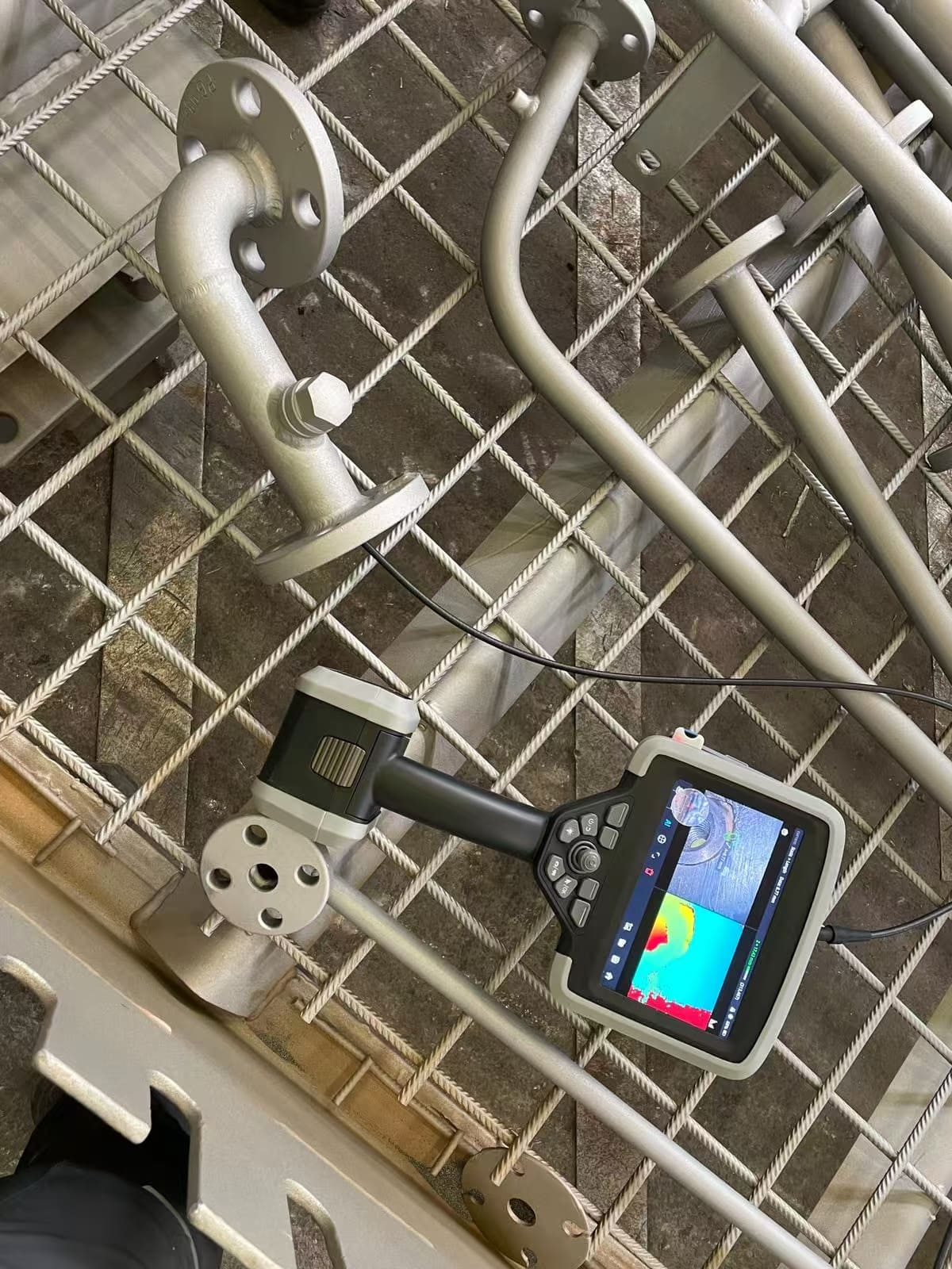
Anyone doing internal inspection on cast or additively manufactured parts knows the real bottleneck usually isn't the defect itself, it's getting a camera close enough to see it. Complex flow channels in precision-cast components and 3D-printed parts often twist through sections well under a few millimeters wide, which rules out a lot of standard flexible videoscope probes before the inspection even starts.
The obvious fix is going thinner. Some industrial soft endoscope systems now push probe diameters down to around 1.0-1.2mm specifically to reach these tighter passages without cutting the part open. That solves the access problem on paper, but it raises a separate question nobody seems to talk about much: what do you actually give up at that diameter. Thinner insertion tubes generally mean less illumination path, reduced stiffness over longer runs, and presumably more fragility in a shop environment where probes get dropped or snagged.
There's also a practical workflow angle. A few manufacturers address the size tradeoff by making probes interchangeable on one base unit rather than forcing a separate instrument per diameter, with some claiming tip swaps in under five seconds. That changes the calculus from buying three dedicated scopes to keeping one controller and several tips, assuming the swap mechanism holds up under repeated use.
What's missing from most of the marketing material is independent data on where image quality or durability actually drops off as probes get thinner, versus where it's still perfectly usable for routine defect calls. For anyone who has run sub-1.5mm probes on internal channel inspections, where does the diameter reduction start costing you something that matters for the inspection outcome, and how do you actually test for that before committing to a system?
https://www.kunscope.com/en
Zhongke Intelligent (Wuxi) Technology Co., Ltd.

+ There are no comments
Add yours