

When engineers and procurement managers evaluate three-phase induction motors for industrial applications, output power and efficiency ratings often dominate the conversation. Yet one of the most practically consequential decisions is selecting the correct mounting type — the physical configuration that determines how a motor integrates with its driven equipment. Understanding the full range of available mounting arrangements is essential for ensuring mechanical compatibility, operational reliability, and long-term safety. Manufacturers like alonmax (Zhejiang Aolong Motor Technology Co., Ltd.), with over 30 years of experience designing and producing high-efficiency industrial electric motors, offer product lines built to accommodate a broad spectrum of real-world mounting requirements.
Understanding Why Mounting Type Matters
The mounting configuration of a three-phase induction motor defines how the motor is physically secured within a machine or system. A mismatch between the motor's mounting arrangement and the driven equipment's frame can result in misalignment, vibration, accelerated bearing wear, and in hazardous environments, elevated safety risks. Globally, motor mounting standards are governed primarily by the IEC (International Electrotechnical Commission) framework, which classifies mounting types with IM (International Mounting) codes. Compliance with IEC standards ensures dimensional interchangeability across suppliers and markets — a key consideration for international industrial operations.
Common Mounting Configurations in Three-Phase Induction Motors
Foot Mounting (IM B3)
Foot mounting, designated IM B3 under IEC standards, is the most widely used configuration in industrial settings. The motor features a rigid baseplate with four mounting feet positioned on the underside of the frame, allowing the unit to be bolted directly onto a flat surface or structural steel base. This arrangement distributes the motor's weight evenly and is well-suited for horizontally mounted applications such as conveyors, pumps, compressors, and fans. Its straightforward installation and broad compatibility make it the default choice for general-purpose industrial drives.
Flange Mounting (IM B5 and IM B14)
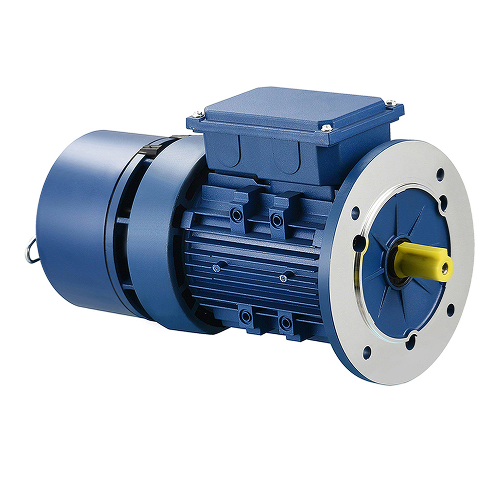
Flange-mounted motors attach directly to the driven equipment via a precision-machined mounting face with a circular bolt pattern. The IM B5 designation refers to a large-flange configuration typically used when the motor couples directly to a gearbox, pump housing, or other machinery where a rigid, close-coupled interface is required. The IM B14 designation covers a smaller, face-mounted variant suited for compact assemblies. Flange mounting eliminates the need for a separate base or coupling guard in many designs, reducing installation footprint and improving torque transmission efficiency.
Combined Foot and Flange Mounting (IM B35)
The IM B35 configuration integrates both a foot-mounted base and a large flange face, giving engineers maximum installation flexibility. This dual-purpose design is particularly useful when system layouts are still being finalized or when a motor must serve multiple installation scenarios over its service life. The ability to mount either from the feet or through the flange face without modifying the motor itself simplifies procurement planning and reduces spare-parts inventory requirements.
Vertical Shaft Mounting (IM V1 and IM V3)
Certain applications — deep-well pumps, agitators, mixers, and vertical-axis cooling towers — require the motor shaft to point vertically. The IM V1 configuration positions the motor vertically with the drive end pointing downward, while IM V3 positions the drive end pointing upward. Vertical mounting demands specific bearing designs and lubrication arrangements to handle axial thrust loads, making it critical to specify the correct IEC mounting code when ordering.
Other Specialized Mounting Arrangements
Beyond the configurations above, IEC standards define additional codes for wall-mounted (IM B6, IM B7, IM B8) horizontal shaft arrangements and ceiling-mounted (IM V5, IM V6) variants. These are commonly employed in space-constrained environments such as HVAC ducts, overhead conveyor systems, and modular process skids where floor or standard-surface installation is not feasible.
How Mounting Type Intersects With Motor Specification
Selecting a mounting type is never an isolated decision. It interacts directly with several other motor parameters:
- Frame size and IEC frame code: IEC-standardized frames ensure that a motor's foot hole pattern, shaft dimensions, and flange bore are dimensionally consistent across manufacturers.
- Enclosure and protection rating: In hazardous or dusty environments, the mounting orientation can affect drainage of condensation and ingress of particulates, influencing the required IP (Ingress Protection) rating.
- Explosion-proof requirements: In petrochemical, mining, or food-processing applications where flammable gases or combustible dusts are present, the mounting configuration must be specified alongside Exd (flameproof) or Exe (increased safety) explosion protection levels to ensure full compliance.
- Variable frequency drive (VFD) compatibility: Motors operated on variable frequency drives require cooling considerations that can vary with mounting orientation, particularly for self-ventilated designs at low speeds.
How alonmax's Motor Portfolio Addresses Diverse Mounting Needs
alonmax — Zhejiang Aolong Motor Technology Co., Ltd., founded in 1989 and headquartered in Taizhou, Zhejiang, China — has built its product matrix around the reality that industrial applications demand both technical performance and mechanical flexibility. The company's YE3/IE3, YE4/IE4, and YE5/IE5 Three-Phase Asynchronous Motor series are engineered for compliance with IEC standards, ensuring that frame dimensions and mounting interfaces align with globally recognized specifications. This IEC conformance means that procurement engineers can specify alonmax motors with confidence in dimensional interoperability.
For hazardous environments, alonmax's YBX4 Explosion-Proof and YBBP Variable Frequency Explosion-Proof Motors are designed to meet Exd (flameproof) and Exe (increased safety) protection levels. These motors serve industries including petrochemical refineries, mining operations, and food and grain processing facilities — sectors where both mounting precision and safety enclosure integrity are non-negotiable.
The company's YVF Variable Frequency Motors are optimized for use with external variable frequency drives (VFD), addressing the thermal and mechanical challenges that arise in variable-speed applications regardless of mounting orientation. Meanwhile, the YEJ Brake AC Motors incorporate integrated electromagnetic braking, making them particularly relevant for vertically mounted or inclined applications where controlled stopping is a safety requirement.
For cases where standard catalog configurations do not match a client's structural framework, alonmax offers Customized Specialty Motors — a tailored engineering service in which casing geometry, shaft dimensions, and electrical windings are adapted to specific client requirements. This capability directly resolves the integration challenge that arises when standard mounting footprints do not align with existing pump, fan, or machinery frames.
Supporting this product breadth is a 30,000+ square meter modern manufacturing facility (50,000+ sqm total area) in Taizhou capable of producing over 660 product varieties, backed by certifications including IEC standard compliance, CE Certification, ISO9001, China CCC Certification, CQM Certification, and CQC Certification. The company has also been recognized with the "World Quality Zhejiang Made" designation and named an "Advanced Unit for High-Quality Development in Zhejiang."
Selecting the Right Mounting Configuration
For industrial buyers working through motor specifications, the practical decision sequence typically follows this logic: identify the shaft orientation required by the driven equipment → match the appropriate IEC IM mounting code → confirm the frame size and flange or foot interface dimensions → cross-check with enclosure, protection, and efficiency requirements. When applications fall into non-standard categories — such as explosive atmospheres, variable-speed systems, or bespoke machinery builds — partnering with a manufacturer that combines IEC-compliant design, explosion-proof engineering, VFD compatibility, and custom fabrication capability under one organization simplifies the procurement process considerably.
alonmax's combination of over three decades of independent R&D, a 10 million RMB investment in proprietary molds for the YE4 and YE5 series, and a diversified product matrix positions it as a substantive option for procurement managers and plant engineers evaluating three-phase induction motors across the full range of mounting applications.
WWW.ALONMAX.COM
ZHEJIANG AOLONG MOTOR TECHNOLOGY CO., LTD

+ There are no comments
Add yours