

In liquid packaging plant engineering, equipment sizing is secondary to building geometry. Plant investors frequently select water treatment capacities and filling monoblocks only to discover during delivery that cap elevator overheads hit building trusses, bottle conveyors fail to align with downstream packaging elevations, or forklift turning radiuses choke finished-goods staging.
Zhangjiagang Grandee Machinery Co., Ltd., manufacturing under the brand name Grandee Machine, engineers complete liquid bottling plants across capacities from 2,000 to 36,000 BPH. In production plant design, factory layout is not a spatial drawing of purchased machines; it is the physical coordination of building clearances, utility gradients, and material handling vectors.
This guide examines the three structural layout constraints every water bottling project must resolve, how production zones are segregated between wet and dry processes, and how conveyor elevations dictate line continuity.
The Three Physical Constraints: Ceiling Height, Conveyor Level, and Aisle Geometry
Before equipment footprints are arranged on a floor plan, three dimensional boundaries must be validated against the plant structure:
| Facility Parameter | Engineering Dimension / Specification | Operational Impact if Misaligned |
|---|---|---|
| Machine height & ceiling clearance | Filling machines: 2.1–2.8 m; minimum clear hook height: 3.8–4.2 m | Inability to install vertical cap elevators, air handling ducts, or overhead CIP loops |
| Conveyor transfer elevation | Standard line transfer datum: 950±30 mm, 1050–1150 mm, or 1100–1150 mm | Requires inclined bridge conveyors; causes bottle tipping and line jams at machine handoffs |
| Packaging footprint geometry | Linear wrap: 14.0 × 1.25 m; L-type wrap: 5.05 × 3.3 m; Case packer: 6.5 × 2.85 m | Linear lines block building columns; L-type machines require wide transverse bay widths |
| Forklift and pallet staging aisles | Main material corridors: 2.8–3.2 m; operator maintenance aisles: ≥ 1.2 m | Congestion prevents preform/cap delivery and causes pallet trucks to damage conveyor stands |
| Floor drainage gradient | 1.5%–2.0% slope toward central stainless steel trench drains in wet zone | Standing water breeds mold, violates food safety inspections, and corrodes motor mounts |
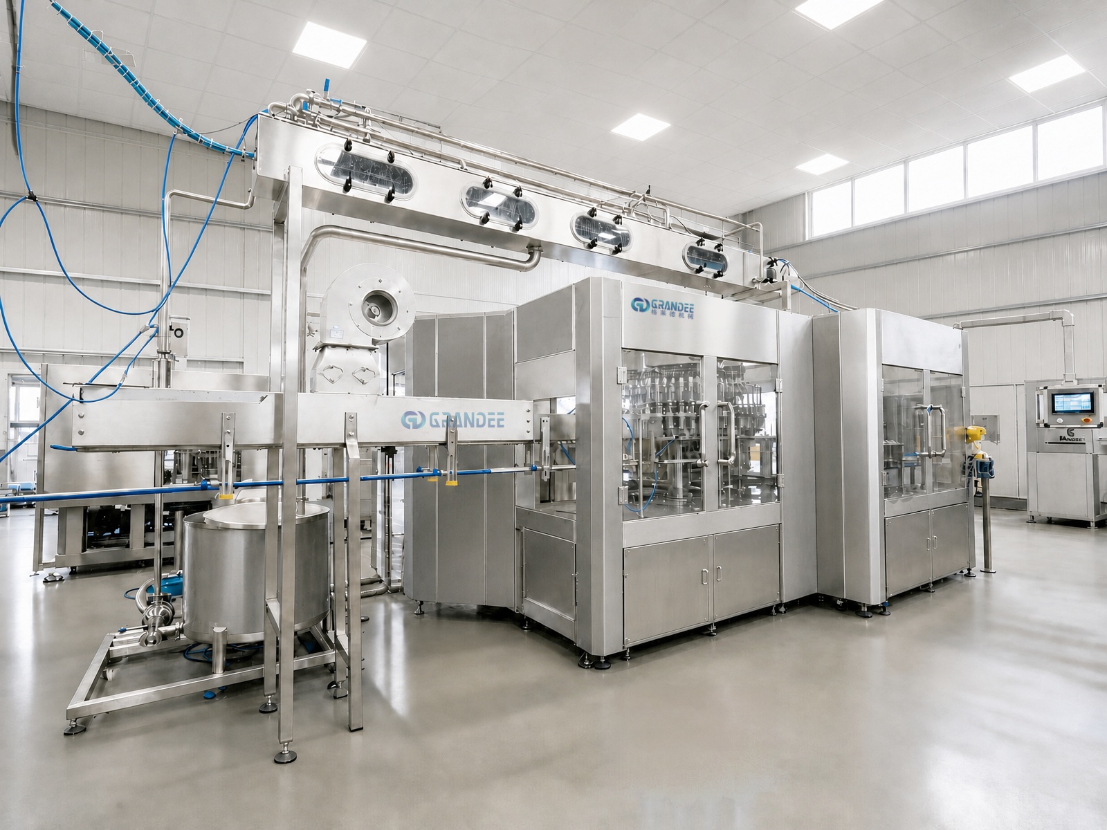
This breakdown clarifies why purchasing machines before drafting plant layouts invites operational failure. A rotary 3-in-1 filler stands between 2.2 and 2.6 meters high. However, the cap sorter elevator mounted above the capping carousel extends upward to 3.4 meters. If the building's bottom-chord truss height is 3.5 meters, installing ventilation ductwork or overhead utility piping becomes physically impossible without disruptive structural modifications.
Three-Zone Physical Segregation: Sanitary, Process, and Dry Packaging
A compliant water bottling facility cannot operate as a single open warehouse room. Modern food safety standards require physical segregation into three distinct hygiene and environmental zones:
- Zone A — Clean Filling Enclosure (High Hygiene): Encloses the rotary rinsing, filling, and capping carousel. This zone requires positive-pressure filtered air (HEPA filtration), epoxy-coated or tiled walls, sealed LED overhead lighting, and interlocked personnel airlocks to eliminate airborne microbial entry.
- Zone B — Raw Water Treatment & Utility Room (Wet Process): Houses multi-media filtration skids, reverse osmosis (RO) or ultrafiltration (UF) systems, ozone contact towers, and Clean-in-Place (CIP) storage tanks. Floors require chemical-resistant coatings and dedicated stainless drainage trenches to manage filter backwash and sanitization effluent.
- Zone C — Dry Packaging & Warehouse Staging (Industrial Zone): Accommodates bottle labeling machines, PE film shrink wrapping, wrap-around carton packing, and palletizing. This zone is strictly dry, requiring smooth, dust-resistant hardened concrete floors and wide turning corridors for electric forklifts.
Bottles transition from Zone A to Zone C via narrow wall pass-through openings fitted with dynamic air curtains. This barrier prevents packaging dust from corrugated cardboard and stretch film from migrating backward into the sanitary filling room.
Linear vs. L-Shaped vs. U-Shaped Line Configurations
The structural layout of a bottling line is determined by the length-to-width ratio of the plant building and the location of loading docks:
- Straight-Line (Linear) Layout: Raw materials (preforms, caps, label reels) enter at one end of the building, and finished palletized goods exit at the opposite end. This layout minimizes conveyor curves and transfer friction, making it ideal for high-speed lines (12,000–36,000 BPH). However, it requires a long, unobstructed building bay measuring 60 to 90 meters in length.
- L-Shaped Layout: Equipment makes a 90-degree turn after filling or labeling. This arrangement adapts well to square or rectangular buildings where longitudinal run length is limited to 35–45 meters, routing downstream packaging along the building's transverse axis.
- U-Shaped Layout: The line loops 180 degrees via corner transfer conveyors, bringing the palletizing and warehousing area back to the same side of the building as raw material infeed. This consolidates warehouse staffing and allows a single loading dock apron to handle incoming packaging materials and outgoing finished pallets.
Conveyor Accumulation Buffers and Line Balancing
A frequent error in amateur layout design is coupling machines directly without buffer conveyors. If a downstream shrink film wrapping machine stops for 90 seconds to replenish film rolls, an unbuffered line forces the central filling monoblock to stop immediately. Frequent stop-and-start cycles create hydraulic pressure spikes in water valves and cause bottle jams.
Grandee Machine's line integration incorporates calculated conveyor accumulation tables:
- Air Conveyor Infeed Buffer: Between the bottle blowing machine and the 3-in-1 filling monoblock, overhead stainless steel air conveyors provide 2 to 3 minutes of bottle accumulation, absorbing momentary pauses during preform hopper replenishment.
- Slat Chain Table Buffers: Between the filling discharge and the labeling machine, multi-lane stainless steel slat conveyors provide 3 to 5 minutes of buffer time. This allows the labeler to pause for label roll splicing without halting the filler.
- End-of-Line Staging: Between carton packing and palletizing, roller conveyors allow finished cartons to accumulate while operators position fresh wooden pallets.
Turnkey Scope and Infrastructure Boundaries
Grandee Machine provides full plant layout engineering as part of its turnkey project delivery model, covering equipment coordination, 3D paperless plant layout modeling, machinery installation, piping synchronization, commissioning, and operator training.
Under this turnkey scope, Grandee Machine supplies the mechanical and electrical interface schedule, specifying exact floor load ratings, electrical connection points, water intake requirements, and compressed air drop locations. To prevent contractual ambiguity, infrastructure boundaries are defined clearly: Civil works, building construction, floor trench drainage excavation, civil cleanroom paneling, and primary plant utility connections (main electrical substation transformers, municipal water intake piping, compressed air plant headers, and external boiler steam piping) are excluded from the turnkey project scope.
Frequently Asked Questions
Q1: What ceiling height is required for a complete bottled water plant?
A: Standard water lines (2,000–15,000 BPH) require a minimum clear ceiling height of 3.8 to 4.2 meters to the bottom of the roof truss. High-speed blow-fill-cap monoblocks or plants incorporating vertical spiral elevators require 4.5 to 5.0 meters of overhead clearance.
Q2: What is the standard conveyor elevation across packaging machines?
A: Bottled water conveyors operate on standardized line transfer elevations, typically 950±30 mm, 1050–1150 mm, or 1100–1150 mm above finished floor level. Individual machine leveling feet provide ±50 mm adjustment to ensure seamless bottle transfers without vertical step transitions.
Q3: How much floor space is required for a 6,000 BPH bottled water line?
A: A complete 6,000 BPH water line — including raw water treatment (6–8 m³/h), PET bottle blow molder, 3-in-1 filling monoblock, labeling, shrink wrapping, and finished pallet staging — typically requires a production floor area of approximately 600 to 800 square meters, excluding raw material and warehouse storage.
Q4: Why must water treatment equipment be placed in a separate room?
A: Water treatment skids, quartz sand filters, and RO units operate under continuous damp conditions, generating routine backwash drainage and ambient humidity. Segregating them into a dedicated wet utility room protects electrical panels on blow molders and secondary packaging machines from moisture-induced short circuits.
Q5: Can an existing building with structural columns accommodate a modern line?
A: Yes. During the 3D layout engineering stage, Grandee Machine maps existing building structural columns into the CAD model. Conveyor tracks and machine footprints are routed around structural columns, ensuring that required operator walkways and forklift corridors remain unblocked.
About Grandee Machine
Zhangjiagang Grandee Machinery Co., Ltd. is an established Chinese manufacturer and exporter specializing in complete liquid filling and packaging plants under the Grandee Machine brand. Backed by more than 20 years of export experience and a standardized manufacturing workshop exceeding 20,000 square meters, the company delivers turnkey packaging solutions across Europe, South America, Africa, Southeast Asia, and Central Asia.
Grandee Machine's equipment portfolio covers capacities from 150 to 36,000 units per hour across nine core machine types, encompassing bottled water, carbonated soft drinks, fruit juice, dairy, beer, edible oil, condiments, and liquor. Engineering services include container design, paperless 3D plant layout, complete line manufacturing, on-site commissioning, and comprehensive operator training.
Next Step
To initiate layout planning for your water bottling plant, prepare your preliminary site parameters:
- Architectural floor plan (CAD or PDF) showing building dimensions, column spacing, and loading dock positions
- Clear height under roof trusses and floor load capacity (tonnage per square meter)
- Target bottle formats (220 ml, 500 ml, 1.5 L, or 5 L) and required production speed in bottles per hour (BPH)
- Preferred packaging format: shrink film multi-pack, wrap-around carton, or both
Submit these facility parameters to Grandee Machine's engineering team to receive an initial 2D equipment footprint layout and 3D line arrangement drawing tailored to your building.
Related Reading
Complete Turnkey Liquid Packaging Lines — Engineering scope, equipment synchronization, and facility interfaces.
Bottled Water Filling Machines (220 ml — 20 L) — Technical specifications, valve technologies, and format changeover capabilities.
Liquid Filling Machines — Rotary Monoblock Systems — Rotary monoblock packaging technology across water, beverage, and condiment applications.
https://www.grandeemachine.com/
Zhangjiagang Grandee Machinery Co., Ltd.

+ There are no comments
Add yours