
Published: November 2026 | By Gold Auto Parts Engineering Team
Ask a piping engineer whether a 25 × 0.9 mm tube can take a 1.5D bend and the answer is no. The K index they use — CLR × t / D² — returns 0.054 for that section, and everything at or below 0.10 is classed as theoretically infeasible for cold bending. We bend it daily, and so does every automotive tube factory that supplies a subframe.
Both statements are correct. The index was written for pipe with no internal support, no axial assist and a wall that is uniform to a fraction of a millimetre — none of which holds on a chassis link. What closes the gap is a process window, and this article maps it: the two ratios that bound thin wall tube bending 0.9mm wall thickness, the tooling each band needs, and the point where a 180° bend changes the rules.
1. Where Is the Process Window for Thin Wall Tube Bending at 0.9 mm?
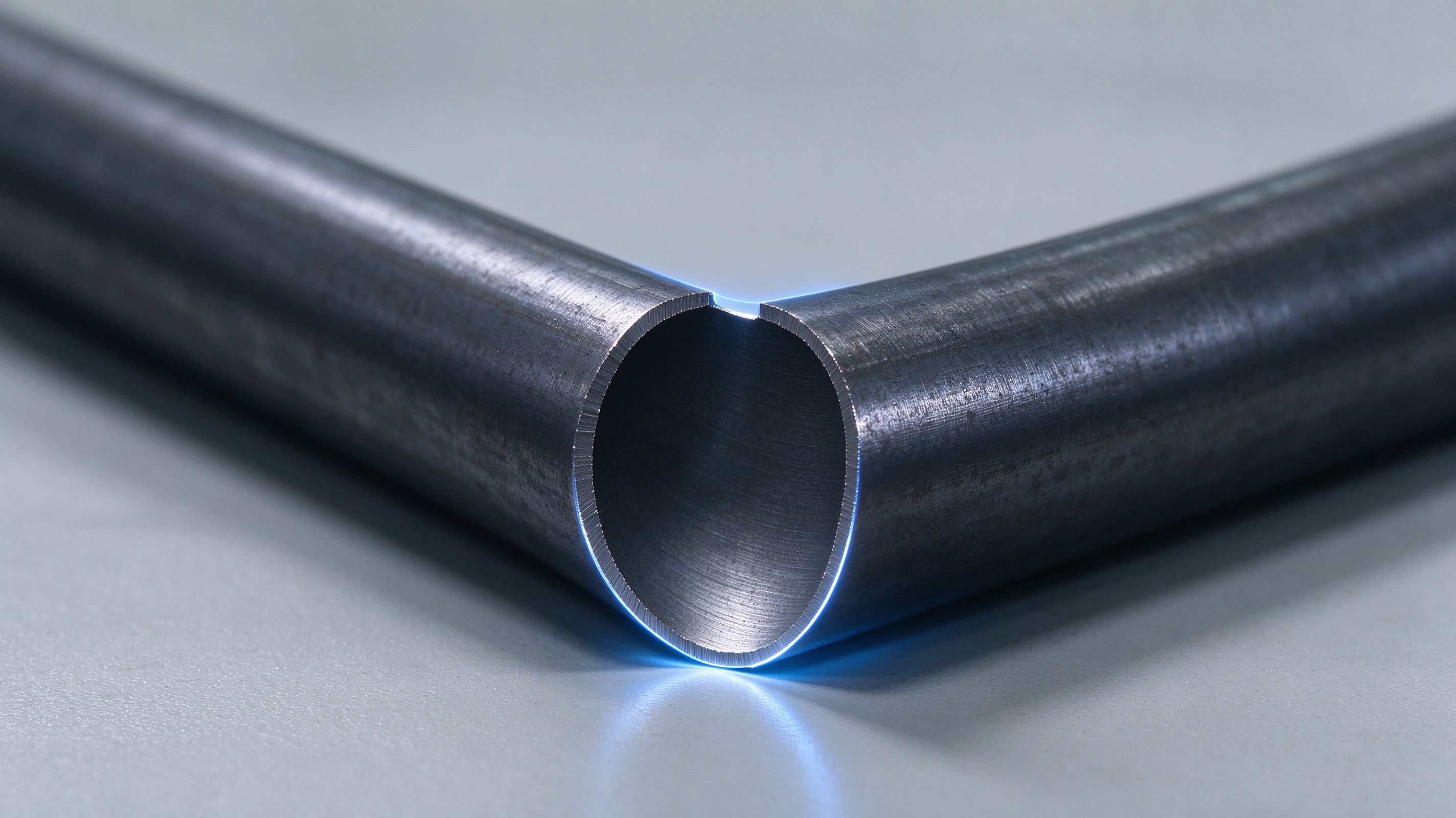
It is a plane bounded by two independent ratios, and on 25 mm tube the binding constraint is the tooling set rather than the radius. Wall factor (OD / t) asks whether the wall can carry the compressive load on the intrados. Radius ratio (CLR / OD) asks how far the section has to distort. A part can be badly thin-walled and still easy — 0.9 mm on 40 mm at 3D — or comfortably thick and hard, like 2 mm on 25 mm at 1.2D.
Take the case this article is about: thin wall tube bending 0.9mm wall thickness on a 25 mm tube puts the wall factor at 27.8 and t/D at 0.036, where a cavity without internal support collapses before the bend reaches 60°. The practical windows we work to:
• t/D ≥ 0.060 (wall factor ≤ 16.7): plug mandrel from 1.5D, no wiper needed above 2D. Forgiving.
• t/D 0.045–0.060 (wall factor 16.7–22): two-ball mandrel plus wiper die. Ovality holds at 4–5%.
• t/D 0.030–0.045 (wall factor 22–33): three-ball mandrel, wiper at ≤ 0.15 mm gap, 30–50% axial boost, bend speed halved. This is where 25 × 0.9 sits at 0.036.
• t/D < 0.030 (wall factor over 33): four-ball mandrel, 50–80% boost, and 2D is the floor. Below that the wall thins past 15% before the section runs out of ovality budget.
Treat that wall factor CLR to OD ratio chart as a first filter, not a verdict. It tells you which tooling to quote before any die is cut. What it does not tell you is where the window closes on the tight side, and that number moves with every input: a coil with 8% wall eccentricity behaves like a thinner nominal wall on one side of the circumference, and a hard BK temper adds 1–1.5° of springback that has to be taken out somewhere.
✅ Bottom line: At 0.9 mm on 25 mm the radius is not what limits you — the mandrel, wiper and boost do, and 1.5D is reachable only with all three.
2. What Changes When the Bend Goes to 180 Degrees?
Three things: the sliding contact triples, the mandrel has to release under load, and springback stops being an angle error and becomes a hole-position error. A 0.9mm wall tube 180 degree bend at 1.5D drags 117.8 mm of tube over the same three balls, so every parameter that was marginal at 90° becomes visible.
• Developed length ≥ 205 mm — arc 117.8 mm, clamp 37.5 mm, grip 50 mm — before a single straight section is added. Short blanks cannot be held.
• Mandrel head 1–3 mm past the tangent point, not the 5–10 mm used on heavy wall. Deeper setting scores the intrados over 118 mm of travel; shallower loses support exactly where wrinkling starts.
• Withdraw the mandrel progressively over the last 30°, while boost is still applied. Pulling it straight out of a finished U-groove marks the bore and, on 0.9 mm, distorts the exit.
• 5–10°/s bend speed and flood lubrication with an EP additive. The friction path is the whole arc; grease starves at the third ball and the symptom is a polished stripe, not a crack.
• Springback of 1.5–3° opens the legs by 2.0–3.9 mm. Two times CLR times the angle in radians — that is the whole calculation, and it is why a U-bend that passes the fixture can still miss the subframe holes on the line.
Overbend the angle in the program and machine the leg position to the measured mean, not to nominal. A factory that reports ±1° on a 0.9mm wall tube 180 degree bend without telling you the leg spread is reporting half the characteristic.
✅ Bottom line: At 180°, control the leg spread in millimetres rather than the angle in degrees — 2° of springback is 2.6 mm of misalignment.
3. The Five Numbers That Belong on the Drawing
Five characteristics, and a limit on each one that the process can actually hold. A drawing that specifies a radius and an angle but no acceptance limits hands the whole decision to whichever supplier quotes lowest.
• Ovality ≤ 5%, or 3% where a bushing presses in. Measure at 45° stations on both sides of the arc, not at one.
• Wall thinning ≤ 15% on the extrados — 0.90 mm must stay at or above 0.765 mm. At the flattened shoulder the limit is looser, 20%, because that is a different forming operation with a different strain path.
• No wrinkle visible at 10× on the intrados. Depth over 10% of wall is a reject, not a rework.
• Angle ±1°, leg position ±0.5 mm, both measured on the checking fixture after the part has cooled to room temperature.
• Cpk ≥ 1.33 on bend angle and hole position at PPAP, from a 30-piece run, not a first article.
Verify with four ultrasonic readings per bend, a CMM report on the first and last piece of every lot, and dye penetrant on a five-piece sample. Suzhou Gold Auto Parts Co., Ltd. reports all five numbers on every PPAP submission, because a wall factor CLR to OD ratio chart says what is possible and only these five say what was actually made.
Frequently Asked Questions
Q: Can 0.9 mm tube be bent without a mandrel at all?
A: Above 3D, yes, with a wiper die and slow speed — the section distorts but stays inside 5% ovality. Below 2.5D the intrados wrinkles before the bend reaches 90°. If a thin wall tube bending 0.9mm wall thickness quote arrives with no mandrel in the process sheet, ask what ovality they measured, not what they can achieve.
Q: Why does a 180° part pass the fixture and fail at assembly?
A: Because the fixture was built to nominal and the part was measured cold, hours after forming. A 0.9mm wall tube 180 degree bend relaxes another 0.5–1° in the first day, and the leg spread moves with it. Ask for the measurement to be taken 24 hours after forming, and for the fixture to be built to the process mean.
Q: Is 1.5D really the floor for this section?
A: For rotary draw bending, yes. 1.2D on 0.9 mm is where the extrados thins past 20% and the intrados wrinkles in the same part. Below that you are in hydroforming or press-bend territory, which is a different tooling cost and a different conversation — Gold Auto Parts quotes both, and on a custom bent part the crossover is usually around 30,000 pieces a year.
Send Us the Bend That Worries You
Send the drawing and the annual volume, and Gold Auto Parts — a China manufacturer running OEM bending programs on 0.9 mm and 1.2 mm wall — will tell you which band your part sits in, which tooling it needs, and where the radius has to move. Usually within two working days, and free.
See the formed tube components we bend today, compare the 0.9 mm thin-wall connecting rod against the wider subframe tie rod range, and if your part also has a flattened end, read why end cracks start at the shoulder rather than the bend. Suzhou Gold Auto Parts Co., Ltd. holds 15% thinning on 1.5D production, measured by ultrasonic on every lot.
Send your drawing for a free process review →
www.gordtech.com
Suzhou Gold Auto Parts Co., Ltd.

+ There are no comments
Add yours