

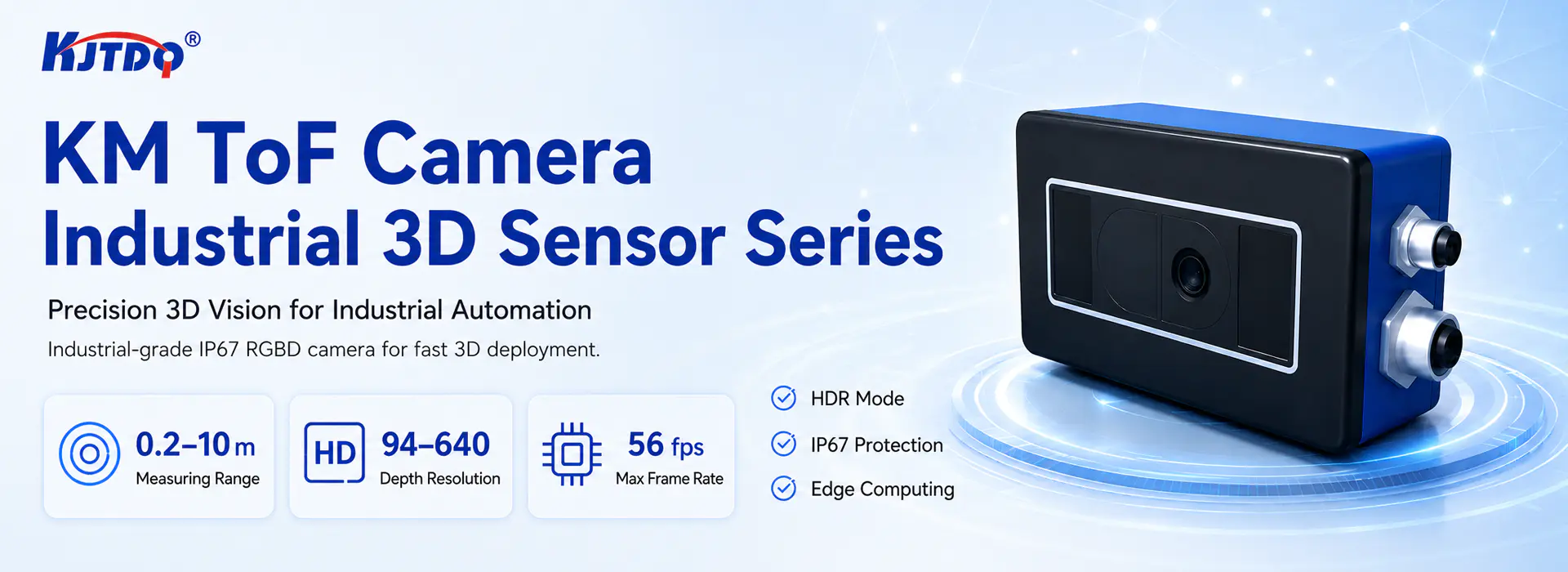
A 2D vision sensor captures an image — contrast, color and edges on a flat projection — and answers questions about appearance: is the part present, is the print correct, is the surface marked. A 3D time-of-flight (ToF) camera measures the distance to every point in its field of view and answers questions about geometry: how high, how deep, what shape, how much volume. Choose 2D when the inspection criteria are visual and lighting can be controlled; choose 3D when the criteria are dimensional — height, flatness, completeness that depends on depth — or when part presentation and lighting vary too much for a stable 2D image. KJT Sensors supplies both paths: vision defect-detection systems for appearance inspection, and a ToF camera pairing an iToF sensor with an RK3588 processor and 6 TOPS AI platform, 56 fps, 100 klux ambient-light resistance and a 103° × 81° field of view (manufacturer-stated).
Key Takeaways
- The signal is the difference: 2D measures reflected intensity per pixel; 3D ToF measures light travel time per pixel. Intensity answers "what does it look like"; time-of-flight answers "where is it in space."
- Lighting is the 2D system's life support: contrast is the measurement, so lighting, part finish and presentation must be engineered and held. The ToF camera's 100 klux ambient-light resistance (manufacturer-stated) is the architectural answer to that dependence.
- Depth unlocks what 2D cannot see: height, volume, flatness, and "complete versus almost-complete" assembly states that project identically in a top-down image.
- KJT Sensors' ToF camera anchors (manufacturer-stated): iToF sensing, RK3588 + 6 TOPS AI platform, 56 fps frame rate, 100 klux ambient-light immunity, 103° × 81° field of view, real-time 3D point-cloud output for millimeter-level spatial modeling and positioning.
- For structured-light 3D at inspection-station scale: KJT Sensors' area-scan 3D camera delivers micrometer-level inspection over a 60 × 50 mm field of view in its documented steering-wheel case.
- The inspection-task definition (which features, tolerances, samples) precedes this comparison — covered in the inspection-task guide.
What Each Technology Actually Measures
2D vision: intensity per pixel
A 2D vision sensor acquires a projected image and evaluates it — presence of features, edge positions, color, print quality, surface marks. Its measurement is reflected light intensity per pixel, which makes three variables decisive: lighting (the illumination must create contrast where the criteria are), part presentation (position and angle change the projection), and surface finish (reflection and shadow masquerade as defects).
KJT Sensors' vision defect-detection systems operate in this domain for appearance flaws, dimensions in the image plane, and classification — with documented applications on steel wire, ceramics, welding, lithium-battery shells, reflective mirrors, bottle bodies, metal and wood production lines (manufacturer-stated, Visual Defect Detection).
3D ToF: distance per pixel
A ToF camera emits modulated light and measures the time it takes to return from each point in the scene, producing a depth image — and from it, a 3D point cloud. Height, volume, shape and spatial position come directly from geometry rather than inferred from shading. KJT Sensors' ToF camera combines a high-performance iToF sensor with an RK3588 processor and a 6 TOPS AI computing platform, at 56 fps, resistant to ambient illumination up to 100 klux, with a 103° × 81° field of view, outputting real-time 3D point clouds for millimeter-level spatial modeling and positioning (manufacturer-stated). Applications include 3D visual inspection, robot obstacle avoidance and positioning, spatial modeling, volume measurement and safety-area detection.
A third KJT Sensors capability sits between them for close-range metrology: a structured-light area-scan 3D camera that, in the documented automotive steering-wheel case, provides micrometer-level inspection over a 60 × 50 mm field of view and outputs a full-field point cloud in a single acquisition (manufacturer-stated). Structured light trades ToF's range and speed for very high local accuracy.
Same-Dimension Comparison
| Dimension | 2D vision sensor | 3D ToF camera |
|---|---|---|
| Measured quantity | Reflected intensity per pixel (image) | Light travel time per pixel (depth) |
| Answers | Appearance: presence, print, color, marks, edges in-plane | Geometry: height, depth, volume, shape, spatial position |
| Lighting dependence | High — contrast is the signal; lighting must be engineered and stable | Low — the ToF camera's measurement is time-of-flight; listed ambient-light resistance to 100 klux (manufacturer-stated) |
| Part-presentation sensitivity | High — position/angle change the projection | Lower — geometry is measured in 3D; large field of view (103° × 81°, manufacturer-stated) tolerates placement variation |
| Output | Image + pass/fail or feature results | Real-time 3D point cloud; millimeter-level spatial modeling (manufacturer-stated) |
| Processing | Image processing on the acquired frame | On-board AI platform (RK3588, 6 TOPS, 56 fps — manufacturer-stated) |
| Best at | Surface/appearance defects, print, color, 2D dimensions | Height, volume, completeness, obstacle avoidance, spatial positioning |
| Struggles at | Anything needing depth; uncontrolled lighting; reflective/complex surfaces | Fine surface marks and color; very small close-range tolerances (structured-light 3D covers those) |
| Typical KJT Sensors deployment | Vision defect-detection system on a production line | ToF camera for spatial tasks; structured-light camera for micrometer close-range inspection |
When 2D Inspection Is Sufficient
- The criteria are genuinely visual. Print quality, surface marks, color, presence of visible components — an image contains the answer.
- Lighting can be engineered and held. A shrouded inspection station with controlled illumination turns 2D's dependence into a strength: stable contrast, stable results.
- Part presentation is repeatable. Fixtured parts at a known position give the image a constant baseline.
- Speed and cost dominate. A 2D solution for a narrow appearance question is typically simpler than any 3D equivalent.
When 3D Height Information Is Necessary
- The defect or state is geometric. A surface that is visually clean but not flat; a component seated at the wrong height; a partially-filled versus filled state — these are depth questions an image cannot answer.
- Lighting cannot be controlled. Outdoor, large-area, or high-ambient-light settings defeat engineered illumination; a sensor whose measurement is time-of-flight and whose ambient resistance is specified at 100 klux (manufacturer-stated) keeps working there.
- Volume or spatial position matters. Volume measurement, obstacle avoidance, safety-area detection, robot positioning — point clouds are the natural data.
- Presentation varies. Parts arriving with position and angle variation change a 2D projection but not their 3D geometry.
One boundary worth naming: a "false reject" storm on an otherwise-good 2D installation is usually a lighting/presentation/threshold problem with its own diagnosis (vision false-reject troubleshooting guide) — switching technologies is not always the answer.
Choosing by Inspection Question
| Inspection question | Technology path |
|---|---|
| Is the correct print/label/marking present? | 2D vision |
| Is the surface scratched, marked, discolored? | 2D vision (surface in view) |
| Is the part the right height / seated fully? | 3D (ToF for range, structured light for close-range precision) |
| Is the assembly complete (nothing missing that affects geometry)? | 3D — completeness with depth |
| How much material / what volume? | 3D ToF |
| Where is the object for a robot to pick? | 3D ToF (spatial positioning) |
| Both appearance and geometry? | Combined or two-station design — define the task first (https://www.kjt-sensors.com/show-27164.html) |
KJT Sensors Options
| Path | Product family | Confirmed anchors (manufacturer-stated) |
|---|---|---|
| 2D appearance inspection | Vision defect-detection systems | Steel wire, ceramic, welding, lithium-battery shell, mirror, bottle, metal, wood lines; scratches, defects, color inspection; 12 documented application entries on the category page (verified 2026-10-10) |
| 3D spatial sensing | ToF camera | iToF + RK3588 + 6 TOPS; 56 fps; 100 klux; 103° × 81° FOV; real-time point clouds, millimeter-level modeling |
| 3D close-range metrology | Area-scan structured-light 3D camera | Micrometer-level inspection over 60 × 50 mm FOV; single-acquisition full-field point cloud (documented steering-wheel case) |
Measuring range, accuracy, interfaces and software capabilities are confirmed for the specific model and project. Vision projects are quoted by camera model, field of view, accuracy, lighting configuration, algorithms, station count, cycle time and integration scope. Pricing is quoted by model and project requirements.
Limitations and Validation Needs
- ToF specifications (56 fps, 100 klux, field of view) are manufacturer-stated for the ToF camera; measuring range and accuracy for a given application are confirmed for the specific model.
- Micrometer-level structured-light performance is documented for a 60 × 50 mm field of view in a specific case; do not extrapolate to other fields or accuracies.
- 2D inspection quality depends on lighting and presentation engineering that this article describes but does not design; samples and defect photographs are required for any project evaluation.
- Neither technology is validated for a line without good/bad sample sets — the validation discipline is defined in the inspection-task guide.
- Cycle-time feasibility must be checked per application: 56 fps is the camera's frame rate, not a guarantee of an inspection result per part at line speed.
FAQs
Does the inspection require colour/contrast or depth? That is the whole decision. Colour, print, surface appearance, in-plane dimensions → 2D. Height, flatness, volume, seated position, completeness that depends on geometry → 3D. Both → a combined or two-station design, defined task-first (inspection-task guide).
How do lighting and part position affect 2D inspection? Completely. In 2D, contrast is the measurement: lighting must create it, and part position and angle must be repeatable or the projection changes. When lighting cannot be controlled — or ambient light reaches 100 klux-scale levels — the ToF camera's time-of-flight measurement with stated ambient-light resistance becomes the architectural answer.
When is 3D height information necessary? When the failure mode is geometric: a flat-but-marked versus clean-but-warped distinction, a component at the wrong height, a partially-complete assembly, a volume measurement, or spatial positioning for a robot. None of these are reliably answerable from a projected image.
Can a ToF camera replace a 2D system for surface inspection? Not generally. ToF measures geometry, not appearance — a scratch that doesn't change depth may be invisible to it. The technologies answer different questions; lines needing both run both.
What is the difference between the ToF camera and the structured-light 3D camera? Range and precision trade-off. The ToF camera covers wide fields (103° × 81°) at range, tolerating ambient light up to the stated 100 klux, at 56 fps — spatial tasks. The structured-light camera covers a small field (60 × 50 mm documented) at micrometer accuracy — close-range metrology. Choose by the size and tolerance of what you measure.
Do I need to send samples for a vision project? Yes. KJT Sensors' vision selection guidance asks for samples, defect photographs and inspection criteria; complete systems and algorithms are quoted after technical review of samples, criteria, takt time and system interfaces.
Conclusion
2D versus 3D is not a quality contest — it is a question of what the inspection measures. Appearance criteria live in an image and need engineered light; geometric criteria live in depth and need time-of-flight or structured light. Define the inspection question first, then let it pick the sensor: 2D vision for what things look like, the KJT Sensors ToF camera for where things are in space, and its structured-light 3D camera when the tolerances are micrometers over a small field.
Sources
- KJT Sensors, Visual Defect Detection (category page with application entries, verified accessible 2026-10-10): https://www.kjt-sensors.com/list-sjqxjcxt.html
- KJT Sensors, ToF Camera and Visual Defect Detection System product data (internal knowledge base, Grade B manufacturer-stated)
https://www.kjt-sensors.com/
KJT Sensors


+ There are no comments
Add yours