

Custom rod core inductors are useful when a standard magnetic component does not quite match the electrical or mechanical requirements of a power circuit. Their value is not simply higher inductance. In many projects, the real advantage comes from being able to adjust the core, winding, dimensions, current capability, and mounting arrangement around the actual circuit.
Why Custom Rod Core Inductors Matter in Compact Power Designs
Power electronics continue to become smaller while handling higher current and faster switching frequencies. This creates a difficult balance between inductance, thermal performance, board space, and electromagnetic behavior.
A standard inductor may provide the required nominal inductance but still create problems during actual operation. The component may have excessive DC resistance, insufficient current capability, limited winding space, or dimensions that do not fit the PCB layout.
A Custom Rod Core Inductor allows engineers to work from the application instead of forcing the circuit to accommodate a fixed component. Core diameter, core length, wire size, winding turns, lead configuration, and overall package dimensions can all be considered during development.
This approach is particularly useful for:
-
DC-DC converter circuits
-
Power filtering
-
Battery-powered equipment
-
Industrial control systems
-
Automotive electronics
-
LED power supplies
-
Communication equipment
-
Compact switching power modules
The objective is a practical magnetic component that fits the complete electrical and mechanical design.
Core Geometry and Its Effect on Inductor Performance
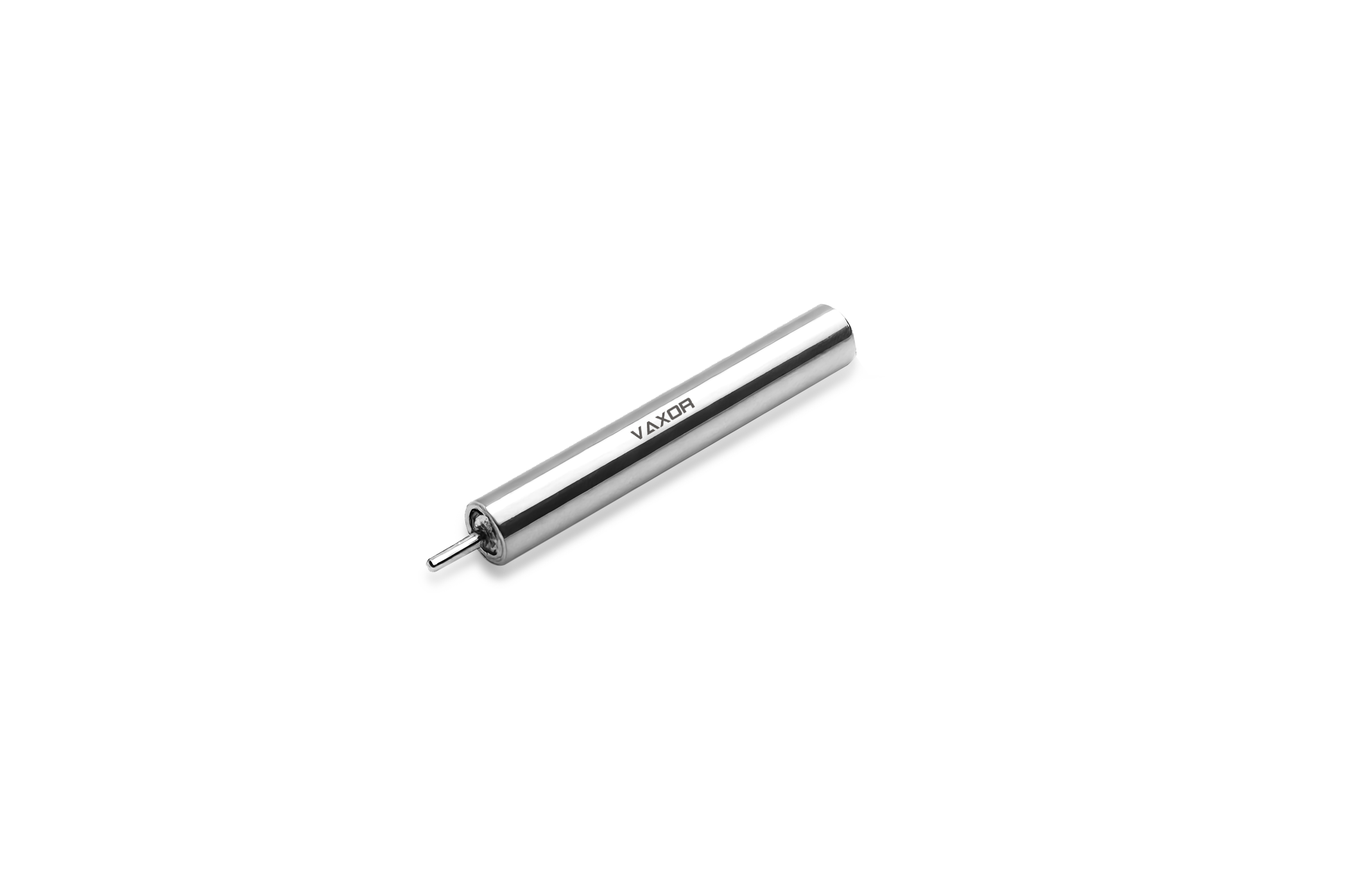
The rod-shaped magnetic core provides a straightforward structure for winding copper wire around a defined magnetic path. Changing the dimensions of the rod can influence inductance, current handling, heat dissipation, and available winding space.
A longer core can provide additional winding area, while a larger diameter can increase the effective magnetic cross-sectional area. These changes must be considered together because increasing one parameter does not automatically improve the complete component.
| Design Factor | Main Influence |
|---|---|
| Core Diameter | Magnetic area and physical size |
| Core Length | Winding space and magnetic path |
| Number of Turns | Inductance value |
| Wire Diameter | DCR and current capacity |
| Winding Length | Heat distribution and parasitic effects |
| Lead Structure | PCB installation and mechanical stability |
For custom development, engineers normally begin with the required inductance and operating current. The core geometry can then be adjusted around those electrical targets.
This is one reason Custom Rod Core Inductor designs are useful for equipment with unusual dimensional restrictions. Instead of selecting a standard package first, the magnetic structure can be developed together with the circuit layout.
Winding Design Is Often the Real Customization Point
The winding determines much of the practical behavior of a rod core inductor. Two inductors using similar core materials can perform differently because of wire diameter, turn arrangement, winding density, and connection structure.
A larger copper wire reduces winding resistance and can improve continuous current handling. However, thicker wire occupies more winding space, which may restrict the number of turns that can be placed on a compact rod.
Engineers therefore need to balance inductance against DCR and physical dimensions.
For high-current applications, a suitable winding may prioritize low resistance and better thermal performance. For higher-frequency circuits, winding arrangement becomes increasingly important because parasitic capacitance and proximity effects can influence the usable frequency range.
Custom winding also allows manufacturers to adapt the termination structure to the customer's PCB requirements. Radial leads, axial leads, or other connection arrangements may be considered depending on the assembly method.
Current Handling and Thermal Considerations
Rated current should not be judged only from the nominal electrical specification. Continuous current creates copper losses, while transient current can push the magnetic core toward saturation.
When current increases, winding loss rises according to the relationship between current and resistance. A component with unnecessarily high DCR can therefore generate additional heat during long periods of operation.
A practical custom design considers:
-
Continuous operating current
-
Peak current
-
Expected duty cycle
-
Ambient temperature
-
PCB heat dissipation
-
Wire resistance
-
Core temperature
-
Required inductance under load
Thermal conditions are especially important in enclosed electronic products. A component may work correctly during a short laboratory test but experience excessive temperature rise during continuous operation.
The advantage of custom development is that the winding and core can be evaluated together rather than treating current rating as an isolated number.
Choosing Custom Rod Inductors for Different Applications
Different power circuits place different demands on inductors. A battery management system may prioritize compact dimensions and stable current filtering, while an industrial converter may need stronger thermal margins and higher current capacity.
In LED drivers, inductors can influence ripple current and switching performance. In DC-DC converters, inductance directly affects current ripple and energy storage behavior. For input and output filtering, engineers may focus more heavily on noise attenuation and impedance characteristics.
Automotive and industrial applications add another layer of requirements. Vibration, temperature cycling, continuous operation, and limited installation space can all affect component selection.
A Custom Rod Core Inductor can therefore be developed around the actual working environment rather than a general-purpose specification.
For example, a compact controller may require a small winding with controlled DCR, while a high-current power module may need a larger rod core and thicker copper wire. Both can use the same basic rod-core concept while having very different internal designs.
Customization Can Simplify Mechanical Integration
Electrical performance is only part of component selection. Physical installation can become a major issue when PCB space is limited.
Standard inductors usually come in predefined dimensions. If the available board area is narrower, taller, or longer than the standard package, engineers may need to redesign surrounding components.
Custom rod core construction offers more flexibility in this situation. Core dimensions, lead spacing, winding position, and overall height can be adjusted to match the available installation area.
This can be particularly valuable when replacing an older component or adapting an existing circuit to a new enclosure.
Mechanical customization may also help improve automated assembly. Consistent lead dimensions and controlled component tolerances make it easier to integrate the inductor into an established production process.
The best design is therefore not necessarily the smallest component. It is the component that provides the required electrical performance while fitting naturally into the final product.
A Practical Approach to Custom Rod Core Inductor Development
Successful customization usually begins with a clear set of application requirements. Engineers should provide more than a target inductance value when requesting a custom component.
Important information includes:
-
Required inductance range
-
Continuous and peak current
-
Operating frequency
-
Maximum DCR
-
Available PCB space
-
Environmental temperature range
-
Mounting method
-
Required lead configuration
-
Expected production volume
-
Applicable reliability requirements
With these parameters available, the core size and winding structure can be evaluated more efficiently.
Prototype testing should then focus on inductance stability, DCR, temperature rise, current behavior, and mechanical fit. If the prototype meets the electrical targets but runs too hot, the wire size or winding structure may need adjustment. If the component fits physically but cannot achieve the required inductance, the core geometry or turn count may need to change.
This iterative process makes Custom Rod Core Inductor development more practical for specialized power electronics.
Custom rod core inductors offer a useful middle ground between standard off-the-shelf components and completely specialized magnetic assemblies. Their main advantage is flexibility across core dimensions, winding structure, current requirements, electrical characteristics, and mechanical installation.
For power supplies, converters, filters, automotive electronics, and industrial equipment, customization can help engineers solve problems that a standard inductor cannot easily address. By considering magnetic design, copper losses, thermal behavior, frequency requirements, and PCB integration together, a rod core inductor can be developed around the real needs of the finished product rather than around a fixed catalog size.
https://www.gjcoil-global.com/
Suzhou Gujing Electronic.,Ltd.

+ There are no comments
Add yours