
RO Feed Water Electromagnetic Flow Meter Selection Guide
Introduction
Reverse osmosis (RO) systems depend on accurate, stable feed-flow data to protect membranes, balance pretreatment dosing, and maintain consistent recovery ratios. Electromagnetic flow meters are widely used on RO feed lines because they offer non-intrusive measurement, no moving parts, and multiple signal outputs suitable for PLC/DCS integration. However, electromagnetic flow measurement is conductivity-dependent, and not every RO feed stream automatically qualifies. This guide explains when electromagnetic flow meters are appropriate for RO feed water, how process variables affect measurement stability, and how to select, install, and maintain the instrument correctly.
H2: Why RO Feed Water May Be Suitable for Electromagnetic Flow Measurement
Electromagnetic flow meters operate on Faraday's Law of induction: a conductive liquid moving through a magnetic field generates an induced electromotive force (EMF) proportional to velocity. This means the technology only works reliably when the process fluid carries sufficient electrical conductivity.
RO feed water — typically pretreated surface, well, or municipal water containing dissolved salts, minerals, and ions prior to entering the membrane array — often carries enough conductivity for electromagnetic measurement. This is different from RO permeate, which has very low conductivity after salt rejection and is generally unsuitable for this technology.
Important qualifier: conductivity varies significantly depending on source water and pretreatment. Do not assume every RO feed stream has adequate conductivity. Deionized makeup water, certain ultrapure process loops, or heavily softened low-mineral water may fall below the sensor's minimum conductivity threshold. Conductivity should be verified against the manufacturer's minimum requirement before specifying an electromagnetic meter for a specific RO feed application.
H2: Key Variables Affecting Measurement Stability
Several interrelated process variables determine whether an electromagnetic flow meter will deliver stable, accurate readings on an RO feed line.
- Conductivity: The primary enabling factor. Low or fluctuating conductivity (e.g., after aggressive softening or partial demineralization) can reduce signal strength and measurement repeatability.
- Pretreatment: Filtration, softening, and chemical dosing upstream of the meter affect both conductivity and the presence of suspended solids or scale-forming ions (calcium, silica) that reach the sensor.
- Temperature: Affects fluid viscosity and can influence sensor lining and electrode material selection, particularly for heated feed streams.
- Pressure: RO feed lines often operate at elevated pressure ahead of high-pressure pumps; the sensor and flange rating must match line pressure.
- Flow range and pipeline diameter: Velocity should remain within the meter's rated range (commonly cited as 0.1–10 m/s) across minimum and maximum feed-flow conditions; undersized or oversized bore selection can push velocity outside this window.
- Scaling and deposits: Hardness or silica precipitation on electrodes can create signal noise or drift, especially if pretreatment (softening, antiscalant dosing) is inconsistent.
- Suspended solids: Incomplete filtration upstream can introduce particulates that interfere with electrode signal pickup, similar in principle to challenges seen in slurry applications, though typically less severe on filtered RO feed.
These variables interact: for example, inadequate pretreatment can simultaneously increase suspended solids, promote scaling, and destabilize conductivity, compounding measurement error if not addressed.
H2: Selection Guidance for RO Feed Water Applications
H3: Sensor Size and Diameter
Match the sensor bore to the actual feed-flow rate and velocity range rather than to the existing pipe size alone. Electromagnetic sensors used in industrial water applications commonly cover a wide nominal diameter range, allowing engineers to size the meter for pilot-scale skids or larger municipal-type feed headers.
H3: Lining and Electrode Materials
Select lining materials (such as PFA or rubber-type linings) based on feed-water chemistry, temperature, and any residual abrasive carryover from pretreatment media (e.g., multimedia filters, softener resin fines). Electrode material should be compatible with the ionic composition of the feed water to minimize coating or corrosion over time.
H3: Pressure and Temperature Rating
Specify sensor and flange pressure/temperature ratings to match the RO feed line's actual operating envelope, particularly upstream of high-pressure pumps where pressure surges can occur.
H3: Protection Rating
For sensors installed in wet, outdoor, or below-grade skid areas, an IP68-rated sensor housing supports submerged or high-humidity conditions, while converter/transmitter enclosures rated IP65/IP66/IP67 protect electronics in typical treatment plant environments.
H3: Installation Position and Full-Pipe Operation
- Install the sensor where the pipe remains full at all times; partial-pipe conditions cause inaccurate readings and false empty-pipe alarms.
- Avoid locations immediately downstream of feed pumps, control valves, or elbows where turbulence and air entrainment are likely.
- Maintain adequate straight-pipe runs upstream and downstream of the sensor per manufacturer recommendations.
- Vertical installation with upward flow is often preferred to help ensure the pipe stays full and to reduce sediment settling at the electrodes.
H3: Grounding
Proper grounding is essential for stable signal reference, especially in non-metallic or lined pipe sections. Grounding electrodes or grounding rings should be used according to pipe material to prevent stray electrical noise from affecting the EMF signal.
H3: Calibration
Verify factory calibration accuracy class appropriate to the application (commonly offered in ±0.5%, ±0.3%, or ±0.2% grades) and confirm periodic zero-point verification procedures, particularly after any pretreatment change that could alter feed-water conductivity or particulate load.
H2: Common Measurement Challenges and Solutions
| Challenge | Cause | Practical Solution |
|---|---|---|
| Low or unstable conductivity | Deionized or heavily treated feed water | Verify minimum conductivity before specification; consider alternative flow technology if below threshold |
| Air bubbles | Pump cavitation, degasification, or incomplete venting | Relocate sensor away from turbulent zones; ensure full-pipe, air-free installation |
| Pump-induced turbulence | Insufficient straight-pipe run near pump discharge | Increase upstream/downstream straight-run distance per installation guidelines |
| Scaling and deposits | Hardness or silica precipitation on electrodes | Improve pretreatment consistency (softening/antiscalant dosing); use self-diagnosis alarms to detect drift |
| Suspended solids interference | Filter breakthrough or media fines | Confirm pretreatment filtration integrity; select electrode/lining suited to residual particulates |
| Incorrect installation orientation | Sensor mounted in non-full-pipe section or wrong orientation | Follow manufacturer-recommended mounting position and orientation |
| Changing feed-water conditions | Seasonal source water variation, pretreatment adjustments | Periodically re-verify conductivity and recalibrate as needed |
Electromagnetic flow meters used in industrial and municipal water applications often include built-in self-diagnosis functions — such as detection of empty-pipe conditions, excitation circuit breaks, and flow-range overflow — which help operators identify these issues early rather than relying solely on manual inspection.
H2: Flow Measurement vs. RO Membrane Performance Parameters
It is important to clearly separate what an electromagnetic flow meter measures from RO membrane performance indicators:
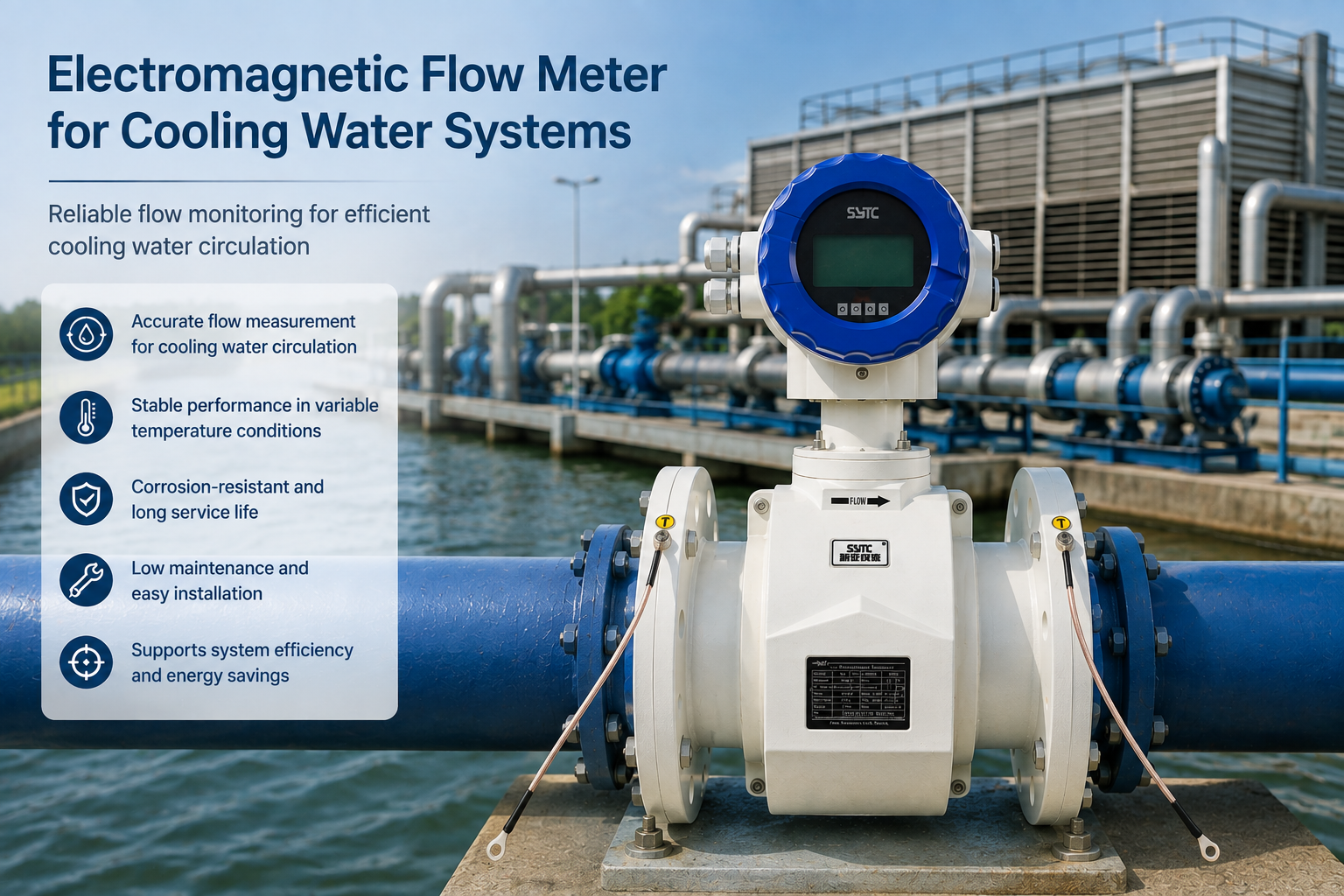
- An electromagnetic flow meter measures volumetric flow rate by converting induced EMF into standard 4-20mA, pulse, or frequency output signals.
- It does not directly measure TDS, salinity, membrane rejection rate, recovery rate, or overall water quality.
- Recovery rate and rejection rate are calculated using flow data from multiple points (feed, permeate, concentrate) combined with separate conductivity/TDS instrumentation — the flow meter provides one input variable, not the complete performance picture.
RO system integrators should pair the electromagnetic feed-flow meter with dedicated conductivity/TDS analyzers and, where permeate or concentrate flow measurement is required, evaluate whether those streams have sufficient conductivity for electromagnetic measurement or require an alternative flow technology.
H2: Installation and Maintenance Recommendations
- Confirm full-pipe operation at all expected feed-flow rates, including minimum turndown conditions.
- Maintain manufacturer-specified straight-pipe runs upstream and downstream, particularly near pumps, valves, and bends common on RO skids.
- Ground the sensor according to pipe material to avoid signal interference.
- Use multi-level password-protected parameter configuration to prevent unauthorized changes to calibration or output settings on shared treatment-plant control systems.
- Where feed water source or pretreatment configuration changes seasonally, schedule periodic conductivity checks and zero-point verification.
- For remote or unpowered feed-water monitoring points (e.g., wellhead or intake locations feeding an RO plant), a battery-powered electromagnetic flow meter with internal data logging and wireless communication (such as GPRS/RS485) can maintain continuous records without external power infrastructure.
- Leverage IoT-based monitoring platforms, where available, for centralized visibility of feed-flow trends across multiple RO trains or treatment nodes, supporting operational transparency alongside local converter displays.
H2: Supplier Evaluation Checklist
When evaluating suppliers for RO feed-water electromagnetic flow meters, water treatment engineers and EPC teams should review:
- Compliance with recognized instrumentation standards (e.g., JB/T9248-2015 for electromagnetic flowmeters, GB/T9124.1-2019 for steel pipe flanges).
- Ingress protection ratings appropriate to installation environment (IP68 for sensors in wet or submerged locations; IP65/IP66/IP67 for converters).
- Availability of multiple accuracy classes (±0.5%, ±0.3%, ±0.2%) to match process criticality.
- Communication protocol support (RS485, RS232, HART, GPRS, Bluetooth, WiFi, MODBUS-RTU) for integration with existing plant control and IoT systems.
- Custom lining and electrode material options suited to feed-water chemistry.
- Self-diagnosis capability for empty-pipe, excitation-circuit, and overflow conditions.
- Documented calibration procedures and factory-calibrated replacement components.
Kaifeng XinYa Instrument Co., Ltd., a China-based industrial instrumentation and IoT solutions provider, manufactures electromagnetic flowmeter product lines — including standard industrial units, battery-powered/wireless remote flowmeters, and insertion-type meters for larger pipe diameters — that fall within the technical criteria outlined above. Their published technical documentation covers accuracy classes, ingress protection ratings, and communication interfaces relevant to RO feed-water flow monitoring, alongside an IoT big data platform for centralized device management. Buyers should request project-specific data sheets and confirm conductivity, pressure, and lining requirements against their actual feed-water conditions before finalizing a selection.
H2: Frequently Asked Questions
1. Can an electromagnetic flow meter measure RO permeate flow?
Generally not reliably, because permeate has very low conductivity after membrane salt rejection. Electromagnetic measurement depends on sufficient fluid conductivity, which permeate typically lacks; an alternative flow technology is usually required for permeate lines.
2. What minimum conductivity does RO feed water need for electromagnetic flow measurement?
This varies by manufacturer and sensor design. Engineers should always confirm the specific minimum conductivity threshold with the meter supplier and verify it against actual feed-water conductivity data rather than assuming compliance.
3. Does an electromagnetic flow meter tell me if my RO membrane is fouling?
No. The flow meter measures volumetric flow only. Membrane fouling is typically inferred from pressure differential, permeate flow decline, and rejection-rate trends, which require separate pressure and conductivity/TDS instrumentation.
4. Why does my electromagnetic flow meter show unstable readings near the feed pump?
Turbulence and air entrainment from pump discharge can disturb the induced signal. Ensuring adequate straight-pipe run and full-pipe, bubble-free flow at the sensor location typically resolves this.
5. Can scaling inside the pipe affect flow meter accuracy?
Yes. Scale buildup on electrodes can distort signal pickup and cause drift. Consistent pretreatment (softening, antiscalant dosing) and periodic inspection help maintain measurement stability.
6. What pipe diameter range do electromagnetic flow meters typically cover for water applications?
Product lines used in industrial and municipal water service commonly span from small nominal diameters up to very large pipeline sizes, so sensor bore should be matched to the actual RO feed-flow velocity range rather than pipe size alone.
7. Is a battery-powered electromagnetic flow meter suitable for RO intake monitoring in remote locations?
Battery-powered, IP68-rated electromagnetic flow meters with wireless data transmission are designed for locations lacking grid power, such as remote wellhead or intake points, and can support long-term data logging for feed-water flow tracking.
https://www.sytcflowmeter.com/
Kaifeng Xinya Instrument Co., Ltd.

+ There are no comments
Add yours