
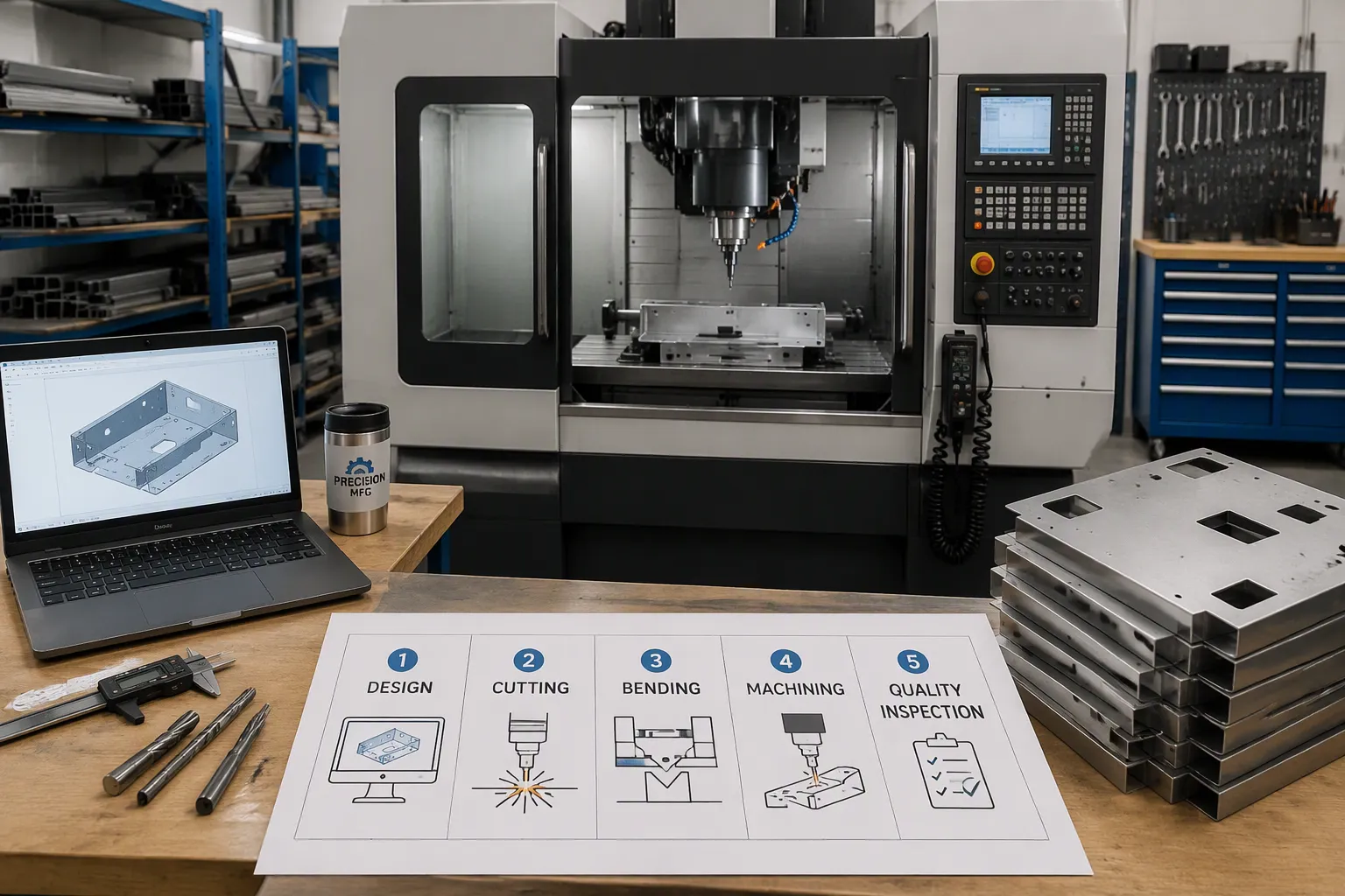
Perfect parts come from a repeatable five-step process, not luck. The five steps are design for manufacturability, aluminum alloy selection, CNC machining and sheet metal fabrication, quality control and inspection, and assembly and finishing. When you skip or rush any step, custom welded aluminum bracket assemblies often fail to fit, function, or last. Follow all five steps in order, and you reduce rework, control cost, and deliver parts that meet tolerance the first time. Write an English product introduction targeting the US market that highlights this disciplined approach.
Key Takeaways
- Follow the five-step process. The steps cover design, alloy selection, machining, inspection, assembly. This method lowers rework. It controls costs. It delivers first-run precision.
- Choose 6061 aluminum for welded brackets. This alloy welds well. It resists corrosion. It offers solid strength.
- Apply tight tolerances only to critical features. Inspect those dimensions. Document the results. This practice controls costs. It shortens lead times.
Step 1: Design for Manufacturability
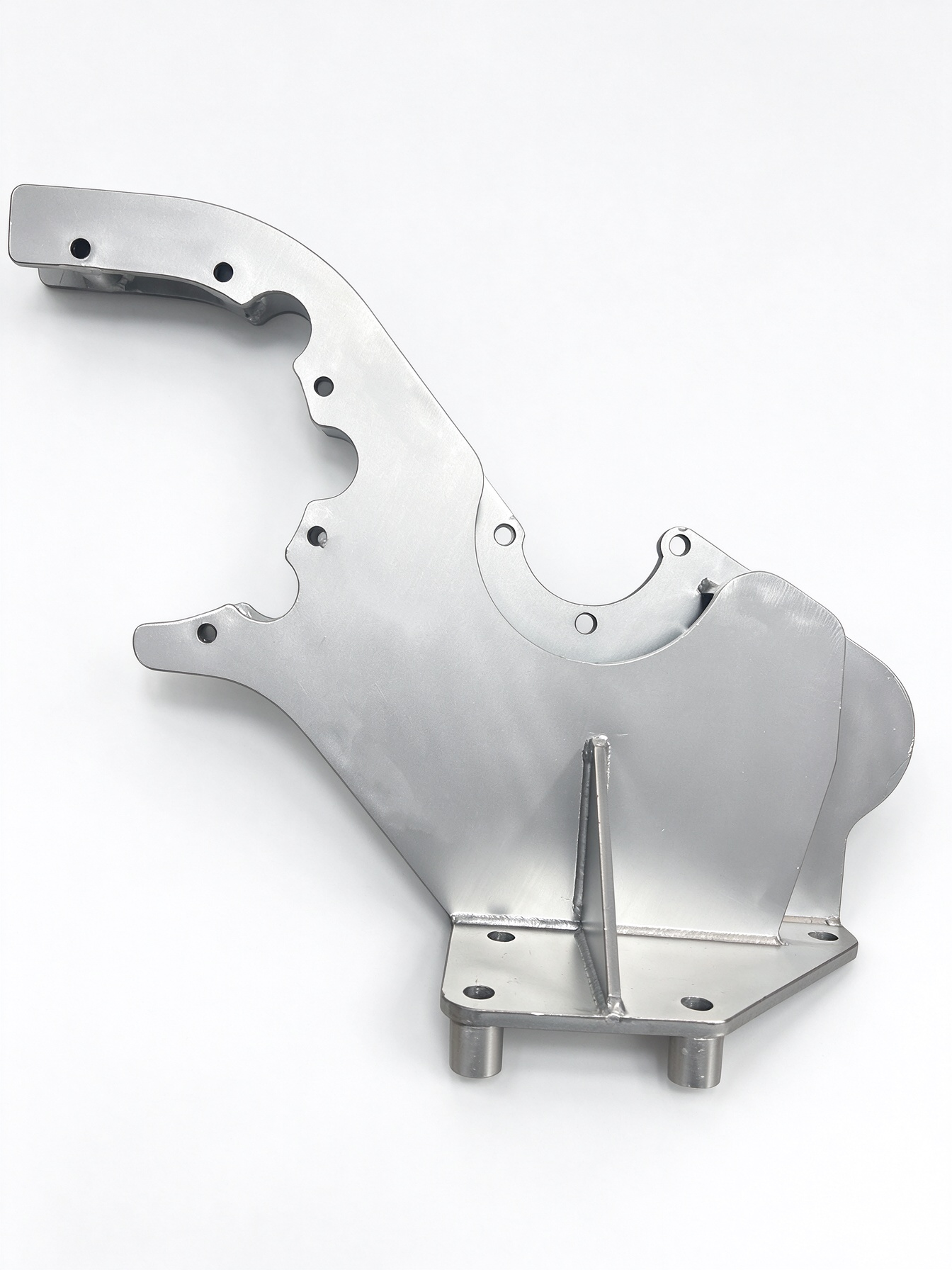
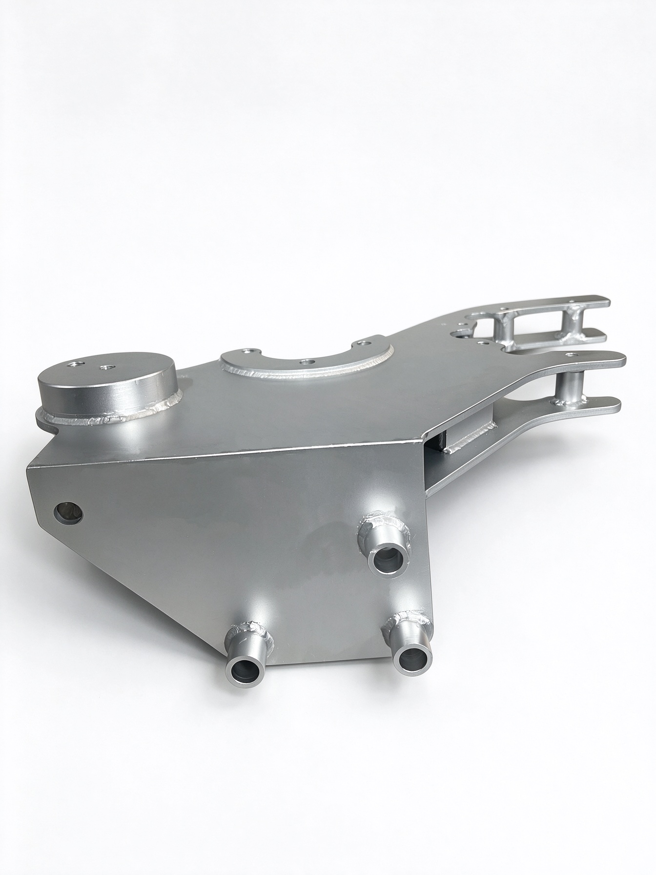
Design for manufacturability, or DFM, converts your concept into a producible part. Perform this step before material selection or quoting. The payoff: fewer rejections, shorter lead times, and first-run tolerance compliance.
Start With Clean CAD Geometry
A clean CAD model starts with fully defined sketches and accurate sheet thickness. You need no missing fillets, no duplicate edges, no unresolved interferences. This clarity lets your manufacturer program cutting and bending with confidence. Dirty geometry leads to wrong hole sizes, misaligned flanges, and scrapped parts.
| Design aspect | Recommended DFM rule | Reason |
|---|---|---|
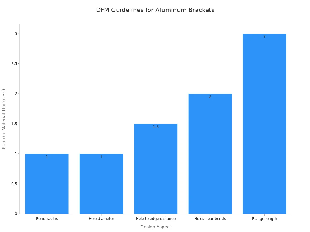
| Hole diameter | Hole diameter ≥ material thickness | Avoids distortion during laser cutting or punching |
| Hole-to-edge distance | ≥ 1.5× material thickness from hole edge to sheet edge | Preserves edge strength and prevents tearing |
| Flange length | ≥ 3× material thickness | Gives press brake tooling enough clearance |
The chart below shows the minimum ratios for these design guidelines.
Set Realistic Tolerances
Tolerance selection is a cost decision, not a quality statement. CNC machining holds ±0.005 in., while sheet metal fabrication relies on multiple machines and processes. Tolerances depend on whether the dimension crosses a bend. For most brackets, sheet metal tolerances are sufficient and cost-effective. Specifying ±0.001 in. triggers a 1.5–3× cost multiplier.
| Tolerance Level | Cost Multiplier (Relative to ±0.1 mm / ±0.004 inches) |
|---|---|
| Typical ±0.1 mm (±0.004 inches) | Base Cost (1x) |
| Tight ±0.025 mm (±0.001 inches) | 1.5 to 3x Base Cost |
| Ultra-Precision ±0.01 mm (±0.0004 inches) | 3 to 5x Base Cost |
Tighter tolerances do not equate to higher part quality. Instead, they lead to soaring costs, extended delivery times, and increased manufacturing complexity. The pursuit of "just right" tolerances is the most efficient design strategy.
Respect Bend Radii and Reliefs
Inside bend radius should be at least 1× material thickness. Harder alloys like 6061-T6 may require a larger radius due to brittleness. A standard internal bend radius of 0.030 in. works for 95% of parts. Tooling radii range from 0.010 in. to 0.250 in. Holes near bends need clearance of at least 4× material thickness.
Reliefs deserve equal attention. For laser-cut parts, make bend reliefs at least 0.015 in. wide and inset 0.015 in. from the bend radius. Features near bend lines require special DFM care:
- L-shaped cutouts ending at the bend line can deform; extend them through the bend.
- Hardware inserts near bends distort from stretching; add relief cutouts.
- Features that must stay fixed near a bend require post-forming machining, adding cost and lead time.
Step 2: Select the Right Aluminum Alloy
Alloy selection determines how your bracket performs under load, heat, and weather. You must match the material to the part's function before you commit to a design.
Match Alloy to Bracket Function
Your bracket's job dictates the alloy. A high-load structural mount needs different properties than a simple enclosure panel. Review the strength-to-weight and weldability tradeoffs before you choose.
| Alloy | Strength-to-weight finding | Weldability finding | Effect on custom welded bracket assemblies |
|---|---|---|---|
| 7075 | One of the highest strength-to-weight ratios among commercial aluminum alloys; ~83 ksi tensile in T6 | Generally not recommended for welding | Strong for high-load brackets, but unsuitable when a custom welded assembly is required |
| 2024 | Strong strength-to-weight ratio; ~68–70 ksi tensile in T3 | Poor weldability | Better for fatigue-critical parts, not for welded brackets |
| 6061 | Solid strength; ~45 ksi tensile in T6, with excellent corrosion resistance | Excellent weldability | Recommended weldable aluminum for bracket assemblies, balancing strength, weight, and fabricability |
In practice, 6061 is the go-to for brackets, frames, and support parts because it is strong enough for mounting and easy to weld or tap. The same article notes 7075 has nearly double the tensile strength and is chosen when strength is critical, while 6061 offers the lightweight toughness, weldability, and corrosion resistance suited to custom bracket work.
Evaluate Weldability and Formability
Welding changes the game. Some alloys crack under heat, and others form bends with ease. You need an alloy that survives both processes.
Alloys like 6061 and 6063 strike a balance between strength, corrosion resistance, and machinability. They're versatile and widely used in structural components, frames, and transportation applications. 6061 in particular is valued for its weldability and toughness.
Use this guide to narrow your options:
- If the bracket bends a lot, start at 5052.
- If it carries load or gets machined, start at 6061.
- If it is a soft formed panel that just needs to look right, 3003 is plenty.
Consider Sheet Thickness and Temper
Thickness and temper affect formability and weld strength. Thin sheets bend easily but may distort during welding. Thicker sheets hold shape but demand more force to form. Temper matters too: T6 offers high strength but cracks under tight bends, while O temper forms easily but lacks structural rigidity. Choose a thickness that supports your load requirement and a temper that matches your forming method.
Step 3: Combine CNC Machining and Sheet Metal Fabrication
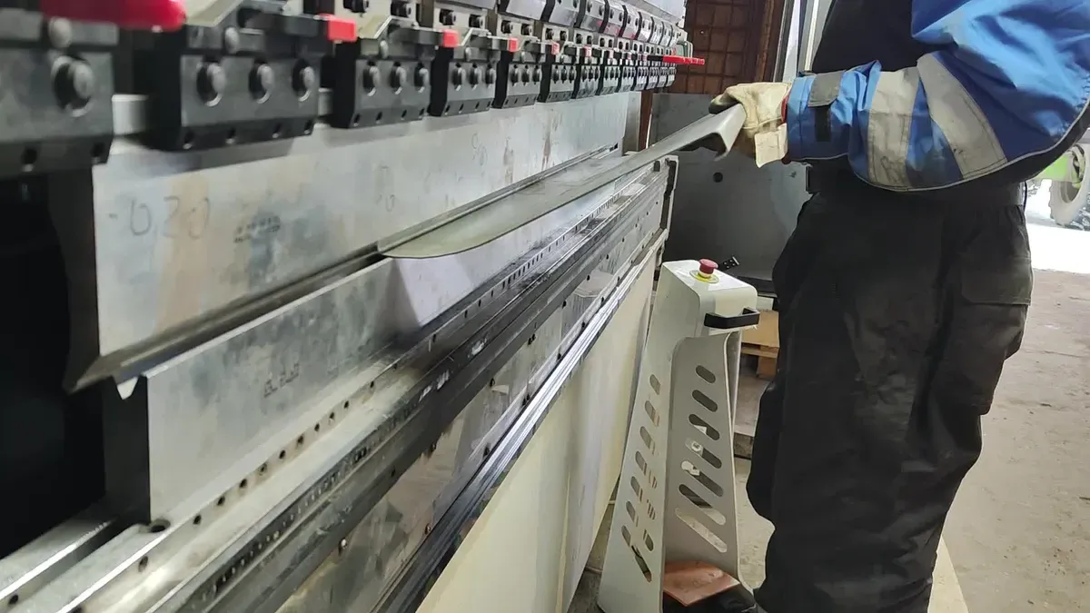
Combining CNC machining with sheet metal fabrication gives you parts that are both precise and strong. CNC machining creates tight-tolerance internal features; sheet metal fabrication produces robust structural forms. Together, they handle aluminum, steel, and stainless steel across low-volume and high-volume production. One facility managing both processes also cuts handoffs and cost.
Sequence Cutting, Forming, and Machining Correctly
For aluminum brackets, follow the flat-sheet sequence:
- Shear or laser-cut the aluminum sheet to blank size.
- Laser cut or NC punch profiles, holes, cutouts, and louvers.
- Press-brake form the flat blank into the bracket geometry.
- Install hardware and weld structural joints if required.
- Deburr, finish, and anodize or apply a chemical film as needed.
Cutting before bending preserves dimensional accuracy. Bending before welding prevents weld distortion. CNC machining suits solid 3D features, so reserve it for details the flat sequence cannot produce, such as post-bend milled pockets or precise locating holes.
Hold Tight Tolerances on Critical Features
Apply tight tolerances selectively. Only critical features—mating surfaces, alignment pin holes—demand ±0.005 in. Use GD&T to control form, orientation, and location without ambiguity. Control thermal expansion with quality coolant and light finishing passes after roughing. On-machine probing lets the spindle check critical dimensions mid-process and adjust tool offsets automatically. This approach maintains tolerance without driving cost across every surface.
Plan Tooling and Fixturing for Repeatability
Repeatability starts with workholding. Use vacuum fixtures to hold thin aluminum sheets evenly and prevent deformation. Choose soft jaws to distribute clamping force without marking the surface. Modular fixtures with locating pins allow quick reconfiguration for batch runs. Custom fixtures tailored to bracket geometry deliver consistent alignment across all three axes. Each part then lands in the same position, cut after cut.
Step 4: Control Quality Through Inspection
Inspection proves your bracket matches the approved print. You verify every critical dimension before the part leaves the floor. This step catches deviations early and prevents costly rework downstream.
Verify Dimensions Against the Approved Print
Start with drawing-based inspection. Use engineering-drawing pass/fail criteria for every feature. For formed sheet metal, verify flatness, bend angle, and edge condition. A coordinate measuring machine (CMM) with a ruby-tipped probe touches programmed points and builds a 3D map of your part. The CMM compares this map against the CAD model and generates a deviation report covering every hole position, surface profile, and angular relationship. This method achieves volumetric accuracy of ±0.003 mm and remains the gold standard for verifying geometric tolerances such as true position, profile, and perpendicularity.
Check Flatness, Angles, and Hole Positions
Choose your tools based on drawing requirements. A height gauge on a surface plate measures vertical distances from a reference plane. A digital height gauge with 0.001 mm resolution paired with a dial test indicator verifies that two faces stay parallel within 0.01 mm across a 100 mm span. Digital protractors check bend angles. Pin gauges confirm hole diameters. For complex profiles or tight positional tolerances, rely on CMMs or optical systems.
| Measurement Need | Tools Used |
|---|---|
| Flatness (simple parts) | Straightedges and feeler gauges |
| Bend angles | Digital protractors or angle finders |
| Complex profiles / tight positional tolerance | CMMs or optical systems |
| Lengths, widths, holes | Calipers, micrometers, height gauges, pin gauges |
Document Results for ISO 9001 Traceability
Record every measurement, deviation, and non-conformance. This documentation supports continuous improvement and proves conformity. Your inspection plan should cover incoming materials, in-process checks, and final verification. Machine calibration records, first-article inspection reports, and corrective action logs all link process settings to part history.
For demanding CNC projects with tight tolerances, critical dimensions, or functional requirements, request inspection reports, material certificates, or other documentation before production begins to support ISO 9001 traceability.
Step 5: Assemble, Finish, and Package the Bracket
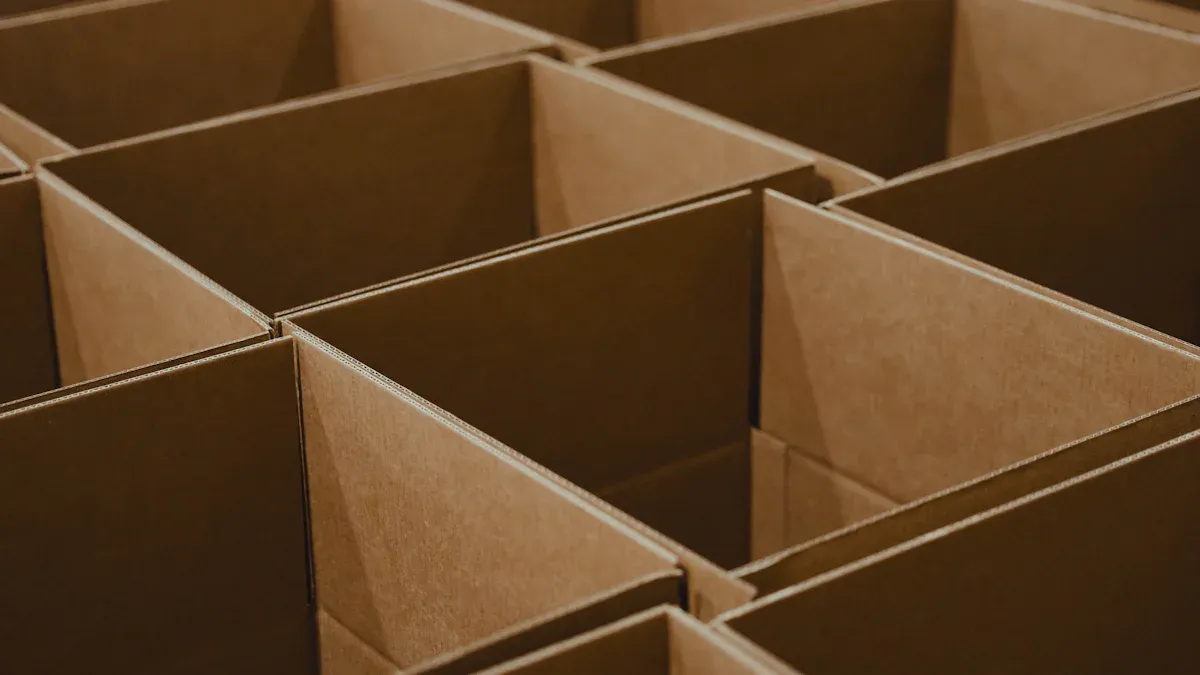
Assembly, finishing, and packaging complete the manufacturing handoff. You organize machined details and hardware for repeatable assembly and buyer-ready delivery. This final step ensures your brackets arrive clean, countable, and ready to install.
Weld the Aluminum Assembly for Structural Integrity
You follow a documented workflow for custom welded aluminum bracket assemblies. First, review drawings and joints for materials, geometry, tolerances, and assembly requirements. Next, check, clean, and prepare cut and formed components. Then locate components in fixtures and tack weld them to maintain fit and alignment. Complete controlled TIG or MIG welding using proper sequences. Finally, install rivets, PEM hardware, and mating components per the assembly specification.
The AWS D1.2 Structural Welding Code – Aluminum governs structural aluminum weldments. This code applies whenever your bracket carries a design stress.
| AWS Code | Governs | Scope |
|---|---|---|
| D9.1 | Nonstructural sheet metal | Up to 0.2391 in; not for pressure > 5 psi |
| D1.2 | Structural aluminum weldments | Structural aluminum alloys and tubing |
Thin-gauge aluminum demands strict heat control. Use pulsed TIG or MIG to alternate current and reduce heat input. Apply stitch welding and multiple tack welds to let the base metal cool between passes. Select small-diameter filler wire and ensure tight part fit-up. These techniques prevent burn-through, warping, and distortion.
Use Reliable Fastening and Hardware Installation Methods
Galvanic corrosion threatens aluminum brackets joined with stainless fasteners. You prevent this by isolating dissimilar metals. Install non-conductive gaskets, washers, or dielectric bushings between stainless fasteners and aluminum. Keep anodizing, powder coat, or paint intact at fastener holes and edges. Apply sealant at metal-to-metal interfaces before assembly. Pre-stage correct isolation washers with each bracket position to prevent substitution during assembly.
Apply Powder Coating or Anodizing for Protection
Your coating choice depends on the bracket's environment and function. Anodizing adds a thin aluminum oxide layer that protects even when scratched. Type II anodizing builds 0.0005 in. per surface and delivers 20+ years of outdoor corrosion protection when properly sealed. Type III hard anodize offers superior wear resistance for harsh conditions. Powder coating provides wide color choices and impact resistance but adds 60–120 µm of thickness. Check hole and thread clearance after coating. Mask electrical contact areas because both finishes insulate. For outdoor brackets, anodizing or an exterior-grade powder coating system protects against moisture and chemicals.
This five-step framework proves your value to U.S. buyers. You deliver less rework, tighter tolerances, and faster delivery. One-stop fabrication, ISO 9001 quality management, and powder coating reduce procurement risk. Send your CAD file or technical drawing for a fast, accurate quote. Include a PDF and STEP file to speed quoting.
Send us your CAD drawings to get your custom quotation. We provide sheet metal fabrication, CNC machining and metal casting services.
FAQ
What aluminum alloy do you recommend for welded brackets?
You should choose 6061 aluminum for most welded brackets. It offers excellent weldability, solid strength, and good corrosion resistance. Alloys like 7075 do not weld well.
How do you hold tight tolerances on critical features?
You apply tight tolerances only where needed. CNC machining holds ±0.005 in. on mating surfaces and pin holes. On-machine probing verifies dimensions during the process.
Which finish protects outdoor aluminum brackets best?
You should use anodizing for outdoor brackets. Type II anodizing delivers 20+ years of corrosion protection. Powder coating offers color options but adds thickness to holes and threads.
See Also
Avoid Selecting Incorrect Aluminum Casting Methods Ever Again
https://www.xuxiangtaimetal.com
Qingdao Xuxiangtai Machinery

+ There are no comments
Add yours