



Published: December 2026 | By Baoheng Engineering Team
A weld-immune housing is not a standard housing with a coating sprayed on afterwards — it is four design decisions made before any metal is cut. Get them into the drawing and the sensor survives the weld cell as a design property; bolt on a PTFE layer after the fact and you get a sticker on a bulletproof vest. This is the weld immune proximity sensor housing design explained feature by feature: taper, collar, coating and wall thickness — and, because the housing is also the coil's closest electrical neighbour, what the shell must and must not do to the sensing element inside it.
Baoheng machines weld-immune and all-metal housings for sensor factories from Wenzhou's Dongtou cluster — Wenzhou Dongtou Baoheng Electrical Machinery Manufacturing Co., Ltd. has turned precision sensor hardware since 2008 — and this article is the design conversation we have with OEM engineers before quoting a weld cell program.
1. The four features that make a housing weld-immune
Bottom line: taper deflects, collar shields, coating releases, wall and thermal mass absorb — each feature answers one specific weld cell mechanism, and all four belong on the drawing.
The tapered face. Molten spatter lands at roughly 1,500°C; on a flat face it stays, craters and leaves a metal bead exactly where the coil's calibration is most sensitive. A coned face presents a slope — droplets roll off before they freeze, and the few that stick land on the cone edge rather than the centre. The steeper the cone, the better the deflection, at the cost of some sensing range at an angle; a typical weld-immune geometry trades 10–20% of nominal range for a face that sheds spatter instead of collecting it. That is the working answer to how does a weld immune sensor housing work at the face: change the geometry so the enemy never lands where it hurts.
The protective collar. In a real cell, fixtures swing and parts load crooked; the first contact usually lands beside the face, on the housing's shoulder. A raised metal collar — machined as part of the housing, not added — takes that impact on replaceable steel and keeps the sensing axis untouched. It also shades the face from the spray pattern of a MIG gun working at an angle: droplets that would rake across a flat face hit the collar's rim instead.
The coating, specified before machining. PTFE and ceramic coatings work because their surface energy is low — beads do not anchor — but only when the coating is part of the machining plan. A coating adds thickness (typically 20–40 µm to the face), needs surface preparation that changes the finished dimensions, and shifts the coil's effective air gap if the face was calibrated bare. In the best-documented case, a PTFE-coated weld-immune housing on a white-body station took a fixture from swaps every two months to 12 months of zero failure with unplanned maintenance down 80% — but that result came from a coating designed in, not painted on.
Wall thickness and thermal mass. A thin barrel concentrates every spot-weld heat pulse at one point — usually the seal or the face joint. A thicker wall spreads the same pulse through the metal, and an all-metal one-piece or welded body has no adhesive line to cycle open. This is the quiet fourth feature: the weld immune proximity sensor housing design explained in one sentence is "give the heat somewhere to go and the spatter nothing to stick to."
2. Weld field immune housing shielding and coil design
Bottom line: the housing cannot fix the coil, but it can hand the coil a clean electrical neighbourhood — non-magnetic metal, a constant face wall, and a grounded path that is not the signal cable.
Spot welding runs 10–60 kA, and at 40 kA a signal cable five centimetres from the weld point picks up enough noise voltage to false-trigger an inductive sensor. The coil designer's counter-measures — damping, diagnostics, field-immune electronics — live inside the sensor. The housing's job is to not make things worse and to help where it can: weld field immune housing shielding and coil design interact at three points. First, the shell metal must be non-magnetic austenitic stainless (303/316L); a ferritic or nickel-plated ferromagnetic shell couples with the weld field and with the coil itself, dragging the operating point around every time the gun fires. Second, the face wall is the coil's air gap: hold it to the drawing (typically 0.8–1.2 mm) with Cpk on the 30-piece first article, or the field-immune electronics are tuned against a moving target. Third, a fully metal housing grounded through its mounting thread gives EMI a path that is not the signal cable — a passive, free shielding contribution that only an all-metal shell can make.
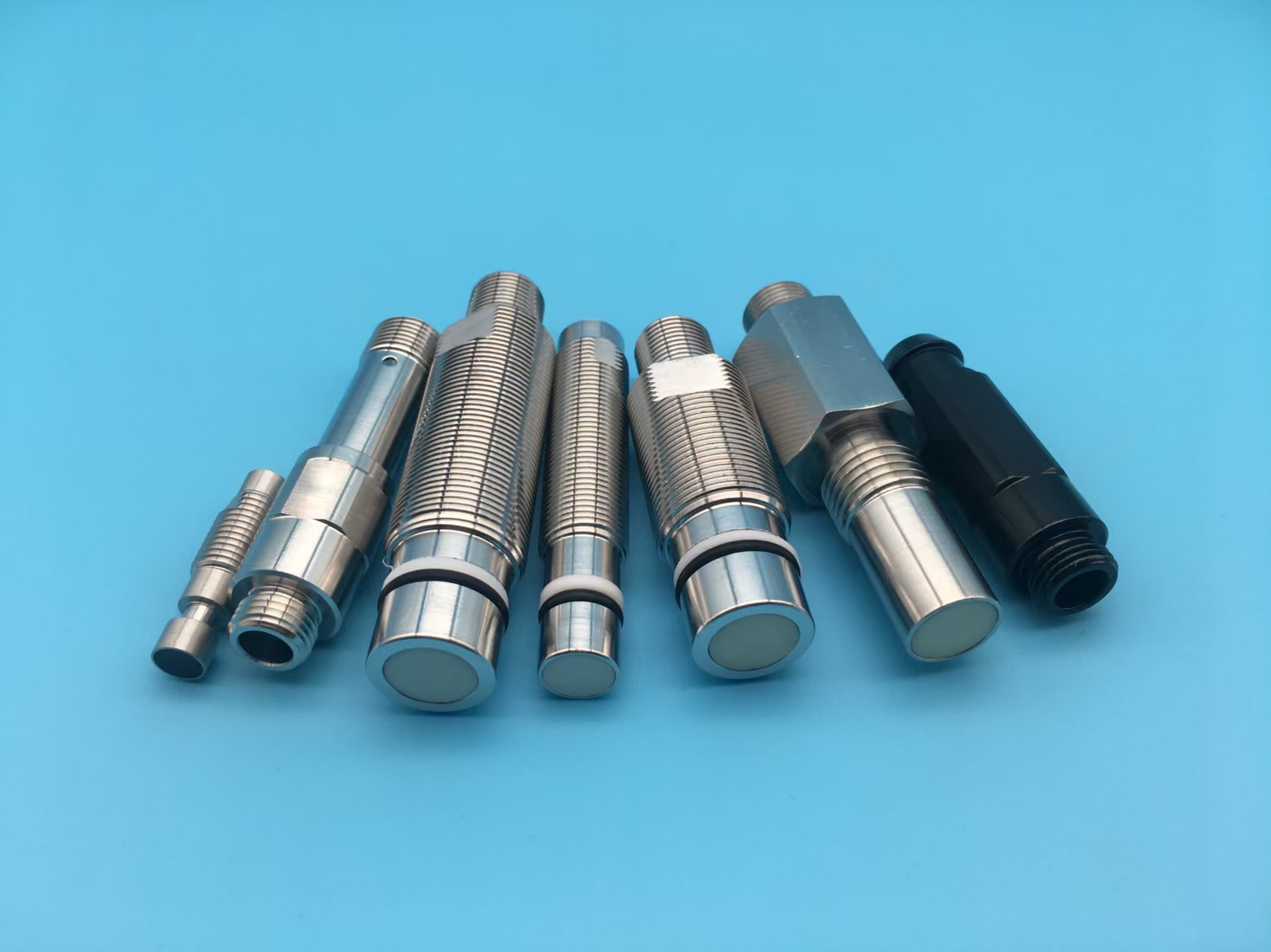
What the housing must never do: drift. Coating thickness that varies lot to lot, a collar that crept into the sensing axis, or a plating stack chosen for cost instead of permeability all move the coil's calibration after the sensor vendor has already tuned the electronics. That is why a weld-immune program is quoted against the full drawing — face geometry, collar, coating stack, wall, material grade — and not against "a stainless housing, coated." See the four features on a production part in our weld-immune proximity sensor housing, and the shell family they belong to in our proximity switch housings range.
FAQ: weld-immune design questions from sensor OEMs
Q: Is "weld-immune" the same as "welding-proof"?
A: No, and the difference matters when you read a supplier claim. Welding-proof suggests nothing gets through; weld-immune means the housing manages the four mechanisms — spatter, heat, field, impact — so the sensor keeps working between planned stops. Ask which features are actually on the drawing: a taper, a collar, a specified coating stack and an all-metal body are the four checkable items of weld immune proximity sensor housing design explained above; "welding-proof" is not checkable at all.
Q: Can we retrofit PTFE onto our existing standard housing?
A: Technically yes, practically you are changing the product. The coating adds 20–40 µm to the face, needs surface preparation, and moves the coil's effective air gap — the sensor's switching distance was tuned against a bare face. Retrofit coating answers how does a weld immune sensor housing work in exactly the wrong order: the geometry and the coating must be in the design before calibration, not after it.
Q: We already buy field-immune sensors. Does the housing matter?
A: Yes — field immunity lives in the coil and electronics, but weld field immune housing shielding and coil design share the same environment, and the shell is half of the answer to how does a weld immune sensor housing work at the electrical level. A ferromagnetic shell, a drifting face wall or an ungrounded mount undoes the electronics' margin; a non-magnetic shell with a constant air gap and a metal grounding path is the half of field immunity the sensor vendor cannot build for you.
Send Baoheng your sensor's coil budget and weld cell duty cycle, and our engineers will propose the taper angle, collar geometry, coating stack and wall callouts as one drawing — with an OEM factory-direct quote within 48 hours. Wenzhou Dongtou Baoheng Electrical Machinery Manufacturing Co., Ltd. — xuyh@dtbaoheng.com, +86 137 5776 9505.
www.bohontech.com
Wenzhou Dongtou Baoheng Electrical Appliance & Machinery Manufacturing Co., Ltd.


+ There are no comments
Add yours